ERTA (also known as FoxTrot) uses two FieldFox units to make long-distance scalar transmission measurements. One unit is the source and the other unit is the Receiver.
In this Chapter
ERTA uses two FieldFox units to make long-distance scalar, tracking transmission measurements. One unit is the source and the other unit is the Receiver.
Communication takes place between the two units with a LAN connection and hard-wired trigger signals. Once the two units are synchronized, the Receiver unit becomes the primary and measures the output of a DUT, while the Source unit responds as secondary supplying signal at the DUT input. The two units, possibly separated by hundreds of meters, step together through the selected frequency range making measurements such as long cable characterization.
With a power splitter at the Source unit, the SA Receiver can be used to measure the reference signal to make a true B/R ratio measurement. Because the reference trace is updated on every sweep, there is no need for static trace normalization. Accuracy is further enhanced with input and output cable corrections. Furthermore, the alignment process keeps the SA receivers calibrated. For information on alignments, refer to the SA mode chapter’s section, “Alignments” on page 219.
—Two FieldFox units with option 209 installed. SA Mode is required for option 209.
—Ethernet LAN cable(s). Either TWO cables that are used to connect both units to the internet or ONE cable that is long enough to connect the two FieldFox units. This may require a cross-over cable.
| When you change network connections, it may take up to 2 minutes for the old address to be replaced by the new address. If the FieldFox was initially assigned an IP address by a DHCP server, and then the FieldFox LAN connection with a DHCP server is removed and is the FieldFox is reconnected to a LAN segment with no DHCP server (such as a direct connect to another FieldFox), the FieldFox may take up to two minutes to self-assign an automatic private IP address. During this connection time the last recognized DHCP address is displayed on the FieldFox, but is invalid. |

—Two trigger cables that are long enough to connect the two FieldFox units, each with SMB (m) to SMA (f) connectors.
—RF cabling to and from DUT.
—Power Splitter (Optional) for enhanced B/R ratio measurements.
Limitations
The following SA features are removed in ERTA mode (Option 209):
—Channel Measurements, Tune and Listen, Interference Analysis, Radio Standards, and Sweep Triggering.
The following SA features are disabled during partnership synchronization:
—Video BW, SwpAcquisition, Frequency Count, Record/Playback, and certain Amplitude Units.
—The only keystrokes allowed on the Source unit are Send Text Message and Exit.
Use the FieldFox Connection Wizard to guide you through the following physical setup.
On the Receiver unit:
—Press Mode then ERTA
—Then Meas Setup 4 then Connection Wizard then Start.
STEP 1: Select [Start] when ready
—Press Start
—At any step, press Exit to end the wizard.
STEP 2: Connect Trigger and LAN cables
—LAN: Connect a LAN cable to each unit. The units can either both be connected to the internet on the same network through a switch or router, or they can be connected directly to each other (a crossover cable may be necessary).
—Trigger signals: On each unit, connect the Ref/Trig Out SMB (m) connector on the FieldFox side panel to the Ref/Trig In SMA (f) connector on the other FieldFox top panel.
—RF connections
Preferred method (pictured above):
—On the Source unit, connect the Port 1 RF Output connector to the input of a power splitter.
—Connect one power splitter output to the Source unit Port 2 RF Input.
—Connect the other power splitter output to the DUT input.
—Connect the DUT output to the Port 2 RF Input of the Receiver unit.
Simplified method (not shown):
—Omit the power splitter. Connect the Source unit Port 1 RF Output connector to the DUT input. The measurement is a raw B receiver. Specs do NOT apply.
STEP 3: Select LAN address of ERTA Partner
The Receiver unit is the primary partner, annotated with RCVR Primary.
The Source unit is the secondary partner, annotated with SRC Secondary.
On the Receiver unit:
—Press ERTA Partner (not specified). The IP addresses of potential FieldFox units are displayed. Select the IP address of the Source unit. If 10.10.10.1 appears, then NO FieldFox units were found. The LAN setting “Obtain IP Address using” MUST be set to DCHP. Learn more in “1G LAN Port (lan0) Settings” on page 895. Also be sure that Opt. 209 has been installed correctly on the Source unit.
—Press Continue.
STEP 4: Test Partnership
—Press Test Partnership. If the Source unit is NOT already in ERTA mode, it will be started, which may take a several seconds. When successful, LAN OK and Trigger OK will appear on the screen.
—If either the LAN or Trigger test fails, then press Clear Test, then Test Partnership to retry the test.
—Optional: Press Send Text Message, then enter a message to send to the Receiver unit. A LAN connection is necessary. For quick communication, custom Keywords can be setup using the FieldFox labeler. Learn how in “Edit Keywords” on page 939.
Any of the following will end the partnership:
—Press EXIT Partnership
—Select Global or Mode Preset
—Change Modes
—Recalling a non-ERTA State file. Recalling an ERTA State file can re-establish a partnership if the Source unit is still on the network at the same location.
—Press Continue.
STEP 5: Measure Jumper Cables
These steps can be used to characterize an Input and Output jumper cable that may be connect the DUT to the FieldFox. The loss of the characterized jumper cables can then be removed from the DUT measurements. The measurements are stored to the internal Cables folder using an auto-generated *.csv filename.
—The Input cable is attached between the Source/splitter output and the DUT input.
—The Output cable is attached between the DUT output and the Receiver unit.
| For optimum flexibility, use the Scale, then More, then Corrections menu to measure, save, and recall cable characterizations. These softkeys are duplicated from the SA Field Strength - Antenna/Cable characterization. Learn more in “Field Strength Measurements” on page 169. |
Figure 26-1 Input and Output jumper cables are measured on the Receiver unit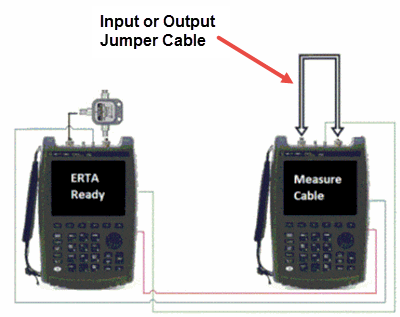
If your DUT input AND output is connected directly to the FieldFox, or you choose to ignore the loss of BOTH jumper cables, then press Skip this step.
Otherwise, press Measure Jumper Cables.
Do the following for both the Input and Output jumper cables:
—Press Skip this step to skip the cable measurement.
—Otherwise, connect the Input / Output jumper cable as shown below, then press Measure Input (or Output) Cable.
—Press Re-measure or Continue.
—Press Apply Corrections Auto to remove the jumper cables from subsequent DUT measurements (Default = Auto).
—Press Done to exit the Connection Wizard.
—On the Receiver unit, press Primary ERTA Partnership. The Source unit enters ERTA mode as the secondary.
Configure Measurement Settings
On the Receiver unit, select measurement settings such as Frequency range, Res Be, Points, and so forth. Zeros pan frequency is allowed even though the frequency is fixed and no stepping is required.
Learn about these settings in “SA Mode Settings” on page 159.
The following traces are provided for your convenience. They are all configured as Clear/Write.
Press Meas 1, then choose one or more of the following:
Softkey | Shown on screen | Description |
|---|---|---|
Input Power | 2 | R receiver. Reference power measured by the Source unit before entering the DUT. |
Output Power | 3 | B receiver. Power out of the DUT measured at the Receiver unit. |
Gain or Loss | 1 | Gain or Insertion Loss. The B receiver data divided by the R receiver data (B/R) This measurement can be displayed accurately with, or without, displaying the R or B measurements. |
Figure 26-2 Input power, Output power, and gain measurement traces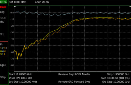
To change the trace numbers of these three measurements, or to select a trace state other than Clear/Write, press Trace 6.
Learn more about Trace Display States in “Trace Display States (SA mode)” on page 213.
Normalize can be used to quickly provide ‘zeroing’ for any of the ERTA (B, R, or G) traces. On the sweep AFTER selecting Normalize, Trace 1 is copied to Trace4. It is then put into View state and subtracted from that input on subsequent sweeps. Any trace (1, 2, or 3) which is set to process that same input (B, R, or G) will therefore be processing normalized measurement data. This continues as long as the frequency span, number of points, and the trace input (B, R, or G) is NOT changed. If any of these settings change, Normalize is deactivated.
How to Normalize the B trace
—Press Meas Setup 4
—Then Remote Source
—Then Normalize ON
Source Tracking Offset and Offset Reversal
Source offset tracking is used to offset the Source frequency from the Receiver frequency by a fixed offset at every tune frequency. This feature is used when the DUT contains a frequency converter.
How to set Tracking Offset and Offset Reversal
—On the Receiver unit, press Meas Setup 4,
—Then Remote Source
—Then Advanced
—Then choose one or both of the following:
—Tracking Offset Enter an offset value.
—OfsTrkReversal Determines whether Receiver Freq is added to or subtracted from the Offset Freq.
——OFF SourceFreq = Offset + RecFreq. Use to measure Upconverters.
——ON SourceFreq = Offset - RecFreq. Use to measure Downconverters. The source sweeps in Reverse direction.
| The Offset Freq. MUST be larger than the Receiver Stop Freq. |
The following settings can be made to reduce measurement noise which improves Dynamic Range.
Increase source power as much as possible while maintaining a leveled source.
How to set Source Power
—Press Meas Setup 4
—Then Remote Source
—Then Source Power
—Then either Max Power or Leveled - Increase source power until the unleveled warning appears. Then decrease power until power is again leveled.
To further reduce measurement noise, on the Receiver unit:
—Reduce Attenuation to 5 dB, then turn the Preamp ON. Learn how in “Preamplifier Control (Opt 235)” on page 168.
—Decrease the Res BW. Learn how in “Resolution Bandwidth (Res BW)” on page 197.
—Set Frequency Reference to GPS on both units. This requires Option 307 (Built-in GPS) and two GPS antennae. The GPS reference can be enabled for several sweeps. Then if you move to a location without an adequate GPS signal, Hold-over Mode will occur. Learn more about GPS as a frequency reference in “Frequency Reference Source” on page 890.
When Source Enable [OFF] is selected, or when Source Mode [CW or CoupledCW] is selected, then synchronization ends and the two partner units revert to general SA (non-tracking) sweeps. However, the units are still in partnership, and other settings continue to be synchronized such as Frequencies, ResBw, and Points.