“Audio (Volume) Control” on page 859
“Display (Settings)” on page 859
“Display Brightness” on page 860
“Full Screen Mode” on page 861
“How to view and change Utilities Settings” on page 862
——“Utilities Softkey Choices” on page 862
——“How to view and change the Frequency Extender (Freq Extnd) Settings” on page 863
“Quick Settings Table” on page 870
“Save and Reset Preferences” on page 872
“Global Settings (Overview)” on page 872
——“Startup Option” on page 874
“Alpha Numeric Editing” on page 879
“File Saving Naming Options” on page 879
“Quick Save Editing” on page 879
“Group Save File Types Editing” on page 880
“CAT (Distance Units)” on page 881
“Discrete Colors Softkey Menu” on page 884
“System Configuration” on page 884
“Options (Licensing)” on page 884
“GNSS (GPS+) and GPS” on page 886
“Frequency Reference Source” on page 890
“Variable Voltage Source (Opt. 309)” on page 892
“Date and Time, Format, and Time Zone Settings” on page 893
“1G LAN Port (lan0) Settings” on page 895
“10G Ethernet (lan1) Settings” on page 898
“FieldFox Package Installer” on page 901
“Date and Time, Format, and Time Zone Settings” on page 893
“Service Diagnostics” on page 903
“Understanding the Fan Controls” on page 906
See Also:
“Install the Lithium-Ion Battery” on page 32
“FieldFox High Temperature Protection” on page 35
The Run/Hold key determines whether the FieldFox sweeps continuously or does NOT sweep, but holds the display results of the last sweep that was performed.
Use Hold to conserve battery power or to allow you to save or analyze the results of a specific measurement sweep.
The current sweep mode is shown on the screen as:
— Continuous
—Hold
— is displayed while a single sweep occurs.
How to perform a single sweep while in Hold
1.Press Sweep 3.
2.Then choose one of the following:
—Single Automatically sets Continuous OFF (Hold) and causes FieldFox to make ONE measurement sweep, then hold for the next Single key press.
—SA Mode ONLY – With Continuous OFF each successive Run/Hold press also causes a single sweep.
—Continuous ON OFF Makes continuous sweeps. This is the typical setting when battery power is not critical.
The Preset key restores the FieldFox measurement settings to a known condition. You can preset the entire instrument, or just the current Mode (CAT, SA, and so forth).
When Preset, the FieldFox CalReady calibration is recalled for use in CAT and NA Modes. Learn more in “CalReady” on page 134.
In addition to all Preference settings, the following settings always survive Preset and Mode Preset:
—External Reference state (see “Frequency Reference Source” on page 890)
—SA Scale and Units (see “Scale and Units” on page 165)
—SA Correction states (see “Field Strength Measurements” on page 169)
—VVM Display Resolution (see “Display Resolution” on page 686)
—Marker Peak Excursion and Threshold (see “What Is a ‘Peak’” on page 830)
How to Preset the FieldFox
1.Press Preset.
2.Then choose one of the following:
—Preset Returns ALL Modes to the factory default settings.
—Mode Preset Returns only the current Mode to the factory default settings. The current settings for all other Modes remain.
User Preset allows you to store custom settings for each mode, then recall the settings when the Preset key is pressed. Your custom settings are saved to a standard State file (UserPreset.sta). However, unlike State files, calibration data is NOT saved. Learn more about State files in “Set File Type and Select Device” on page 919.
How to set User Preset
1.Make your custom settings for all modes.
2.When finished, press Preset.
3.Then Save User Preset, then select Yes to confirm.
4.Then User Preset ON
How to recall User Preset
—Press Preset.
—Then choose from the following:
—Preset (User) The entire UserPreset.sta file is recalled. ALL modes assume the settings that were in place when the User Preset was saved. The active mode is the mode that was visible when the file was saved.
—Mode Preset (User) The settings for only the current mode are recalled from UserPreset.sta.
| —Only the instrument settings are saved to UserPreset.sta. No trace data or calibration data is saved. —User Preset ON / OFF is saved as a Preference setting. Like all preferences, this setting survives a FieldFox shut down and power ON. Therefore, when User Preset is ON during shut down, the FieldFox will load UserPreset.sta when it is powered ON. —To return to Factory Preset, select User Preset OFF. The contents of UserPreset.sta remain stored on the FieldFox. When User Preset is OFF, you can also set the Startup Mode preference that determines which mode will be visible after powering ON. Learn more in “Startup Mode” on page 874. |
System volume control is a FieldFox global setting which sets speaker volume for ALL success beeps, key press clicks, and individual features that use the FieldFox speaker, such as SA Mode Tune and Listen.
The volume control setting remains through a FieldFox Preset. To cause your volume control setting to remain through a FieldFox shut down, save the setting as a Preference. Learn how in “Save and Reset Preferences” on page 872.
How to set the FieldFox Volume Control
1.Press System 7
2.Then Volume
—Use the arrows, the rotary knob, or numeric keypad to enter a value between 0 (lowest volume) and 100 (highest volume).
—Press Volume again and select Mute to quickly turn OFF the speaker volume.
—Press Volume again to set volume ON to the previous volume control.
You can adjust the FieldFox for optimum viewing in a wide range of lighting conditions.
Display settings are persistent after a FieldFox shut down. Save the display settings as Preferences. Learn how in “Save and Reset Preferences” on page 872.
| Clean the transflective screen with gentle and minimal wiping using Isopropyl alcohol applied to a lint-free cloth. |
Change the brightness of the background.
1.Press System 7 > Display > Brightness
2.Use the arrows, the rotary knob, or numeric keypad to enter a value between 0 and 100%.
Change Display Colors to alter the viewing scheme.
1.Press System 7 > Display > Display Colors
2.Then choose one of the following:
Indoor | |
Outdoor Dusk | |
Outdoor Clouds | |
Outdoor Sun | |
Night Vision |
You can set width of all displayed traces on the FieldFox. This may allow better viewing or enhance the look of screen images. This setting can be saved with Preferences.
How to set Trace Width
1.Press System 7 > Display > More > Trace Width
2.Then choose one of the following:
—Normal - Standard width.
—Wide - Enhanced width.
A custom title can be made to appear in the upper-left corner of the FieldFox screen. The title can contain up to approximately 65 alpha-numeric characters. To view the Title area, see the Screen Tour in “Screen Tour” on page 51.
How to add or edit a Title
1.Press System 7 > Display > Title
2.Then enter or edit a title using the FieldFox labeler. This is the same labeler function that is used to name files. Learn how to use the labeler in “How to use the FieldFox labeler ” on page 916.
3.Then Title ON OFF to make the title appear and disappear from the screen.
During a file save operation, keywords can be quickly appended to other text to create unique filenames. The Edit Keywords feature allows you to create custom keywords. Learn all about Edit Keywords in “Edit Keywords” on page 939.
Full Screen Mode maximizes the display of trace. The screen annotations and the soft keys are removed.
1.Press System 7
2.Then Full Screen
To Exit full screen Mode, press any key.
FieldFox utilities settings will not survive a shut down. When your FieldFox is turned OFF, then back ON, these settings default to their factory settings.
How to view and change Utilities Settings
—Press System 7
—Then Utilities Opens the Utilities softkey menu.
Then choose one of the following:
—Mapping – (Requires Option 352) opens a menu of softkeys that enables the Indoor / Outdoor on–the–box mapping features. Refer to Chapter 16, “Indoor and Outdoor Mapping – Option 352 (Requires Spectrum Analyzer Mode (Option 233), and GPS Receiver (Option 307)).”
—EMF Antennas – opens a menu of softkeys that enables the triaxial antenna feature, for use in EMF measurements. Refer to Chapter 15, “USB Antennas – Full Capability Requires EMF Option 358, and either SA mode (Option 233 Mixed Analyzers) or OTA—LTE FDD (Option 370), LTE TDD (Option 371), 5G NR / 5G NR EVM Conducted / 5G TF (Option 378).”
—Freq Extnd – opens a menu of softkeys that enables frequency extender feature, for use with VDI and OML heads. Refer to “How to view and change the Frequency Extender (Freq Extnd) Settings” on page 863.
| IMPORTANT! The Frequency Extender (Freq Extnd) is only active (available) when one of the following modes are enabled: SA/RTSA/IQA/OTA/VSA (via the Remote Server feature). When VDI and OML millimeterwave extenders are used, Cable and Antenna corrections, if On, are included in eCorr, or Extended Corrections. |
| The OML millimeterwave extenders has been discontinued and are no longer supported. Keysight recommends VDI as the preferred alternative. For more information on the supported Keysight VDI frequency extender modules, please visit: https://www.keysight.com/us/en/product/N9910XVDI/mmwave-frequency-extenders-for-fieldfox-handheld-analyzers.html |
How to view and change the Frequency Extender (Freq Extnd) Settings
The following are the only supported modes for the frequency extender feature: SA (Option 233), mixed analyzers, RTSA (Option 350), IQA (Option 351), OTA (Option 370/378), and VSA (via the Remote Server feature). IMPORTANT! When using a frequency extender with the FieldFox you need to manually set the LO power: – When using the mixer, the LO power should be reduced to –12 dBm and – Reduce frequency span to make measurements until the “unleveled power” message goes away (requires ≥A.12.40 firmware) IMPORTANT! Due to limitations in the OML hardware, the heads have a 6 GHz frequency span. Examples Using a 24 to 40 GHz mixer, you can sweep: —24 to 30 GHz and 25 to 31 GHz, but not —24 to 31 GHz Assuming the same 24 to 40 GHz mixer, using OTA mode, you can —Set a CC0 to 24 GHz and CC1 to 31 GHz, but not —CC0 to 4 GHz and CC1 to 32 GHz, because you have to remain within the mixer’s band 89600 VSA (via the Remote Server feature) are compatible with the frequency converter heads, but cannot apply or edit the frequency head corrections.
If you upgrade your FieldFox firmware to ≥A.12.40, but find you are unable to adjust the LO power level to –12 dBm, refer to “Erase User Data” on page 904.
For this section, refer to Figure 31-1 on page 867, Figure 31-2 on page 868, Figure 31-3 on page 868, Figure 31-4 on page 869, Figure 31-5 on page 869, and Figure 31-6 on page 870.
These settings are used to set up a frequency extender head (e.g., VDI, OML head). The frequency extender feature can be used in OTA FR2 measurements. See also, Chapter 13, “Over–the–Air Measurements (OTA) – LTE FDD Option 370, LTE TDD Option 371, 5G NR / 5G NR EVM Conducted / 5G TF Option 378.”
The frequency extender heads are an external down converter that extends the FieldFox's range. The frequency extender head makes use of the FieldFox's source and uses USB port for power. The FieldFox support for the frequency extender head includes:
— The frequency extender heads are compatible with to SA, IQA, OTA, RTSA, and 89600 VSA (via the Remote Server feature—with VSA license). The OML frequency extenders have approximately 4 to 10 dB of gain depending on the mixer and frequency.
—The USB ports are used to supply power to the head
—Port 1 is used to supply an LO signal to the head. The LO signal is automatically generated, using the internal source. Therefore the application disables normal Port 1 access to the internal source. But, automatic alignments of the SA Receiver still remain active using an internal path for the source.
—Port 2 is where the head delivers the downconverted signal to the SA receiver.
—High Sensitivity ON OFF selection: able to choose between showing largest span (wide) available (6 GHz) or best noise floor (narrow).
Frequency Extender Procedure:
General Comment on Frequency Converter Usage:
OML heads are limited to 6 GHz span.
Example:
If you are using a 24–40 GHz OML head you can sweep:
—24–30 GHz and 25–31 GHz, but not:
—24–31 GHz
But, in OTA mode, because each frequency is set separately, you can set CC0 to 24 GHz and CC1 to 31 GHz.
But, you cannot set CC0 to 4 GHz and CC1 to 32 GHz. You have to stay within the band of the OML mixer (24-40 in this example), if you are enabling an external head.
1.Press System 7 > Utilities > Freq Extnd > Select Freq Extnd Head
2.To select the frequency extender head, use the numeric keypad, arrows, or rotary knob to change the value.
3.Press Recall File to make the highlighted head the current selection.
4.Press Freq Extnd ON OFF to ON to enable the frequency extender head. When a compatible mode is enabled, all supported modes annotate Freq Extnd at the bottom of the display. See also, step 8.
5.Optional: Press High Sensitivity ON OFF OFF is selected for maximum span (up to 6 GHz). Narrow is selected for lowest noise floor for a given RF input (100 MHz). Default is OFF (maximum span – 6 GHz).
6.Optional: Press Setup Corr Auto Edit SA when Auto is selected the default corrections for a frequency converter head are automatically loaded ("...Default.csv"). These corrections are defaults for the specific head, to improve nominal accuracy of the amplitude readings, but this accuracy is not specified. Press Edit SA, when you want to view or edit the corrections using the SA mode corrections. This state stops all auto-loading of the default corrections. Refer to step 8.
The other non-SA supported modes do not allow viewing or editing of the corrections, but they all share the same corrections.
Therefore, any manual changes to the corrections (using SA via Edit SA) are then used by other supported modes (RTSA/IQA/OTA) as well.
7.Optional: Press Apply Corr ON OFF OFF is selected to not apply the default nominal file corrections. Press to apply corrections for the Converter, all supported modes will apply corrections and annotate "eCorr" in the left panel. The corrections applied (regardless of mode) are either default/nominal (if Auto loading was used) or custom/specific (if manual editing Edit SA was used). Default is OFF.
8.Press Mode > and then your preferred mode for testing.
IMPORTANT! The softkey menu for editing of the frequency converter correction files is only available when the FieldFox is in SA mode. |
—Optional: If you pressed Edit SA in step 6 above and want to display and to edit a "*.csv" corrections file then:
—Press Scale/Amptd > More > Corrections > OML Converter then:
a.Converter to enable/disable the frequency converter corrections.
b.Edit Converter to opens a corrections table of the currently selected file (*.csv).
To select a setting/value to edit, use the numeric keypad, arrows, or rotary knob to change the value.
Refer to Figure 31-4 on page 869.
c.New to opens a corrections table of the currently selected file (*.csv), but enables you to create a new converter corrections file. Displays "Overwrite existing Converter data?" Then choose:
——Yes to clear all of the frequency converter correction table’s values and enter your own.
——No to leave the current correction table values and edit just some of the entries.
To select a setting/value to edit, use the numeric keypad, arrows, or rotary knob to change the value.
Refer to Figure 31-4 on page 869.
d.Save Converter opens a ’labeler’ menu where you can name and save your frequency converter corrections file (*.csv) to the default [INTERNAL]:\Converter folder.
e.Recall Converter opens a menu where you can recall a frequency converter corrections file (*.csv).
f.Storage Device opens a menu where you can change the storage location of your frequency converter correction files (*csv). (Default = Internal. Else press, SD Card or USB.)
Figure 31-1 FieldFox with OML Downconverter
Figure 31-2 FieldFox Frequency Converter High Sensitivity (ON: Narrow—Lowest Noise Floor—Displayed)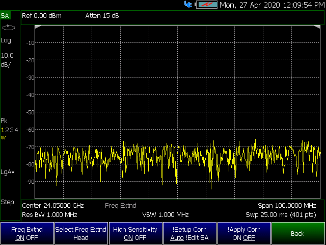
Figure 31-3 FieldFox Frequency Extender Select Frequency Extender Head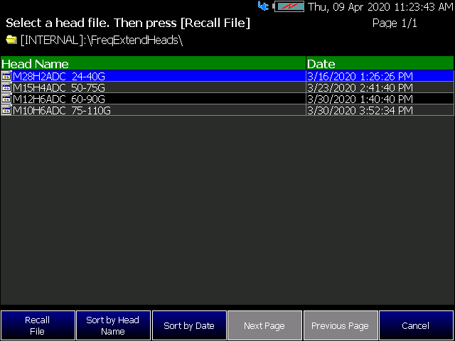
Figure 31-4 FieldFox Frequency Converter Corrections Table
Figure 31-5 FieldFox Frequency Converter (Freq Extend) On And Corrections (eCorr) Enabled (SA mode shown; other compatible modes are similar.)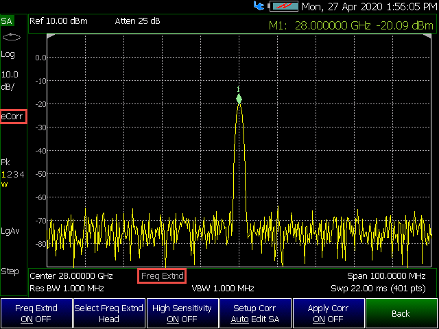
Figure 31-6 FieldFox Frequency Converter (Freq Extend) On And Corrections (eCorr) Enabled (RTSA mode shown; other compatible modes are similar.)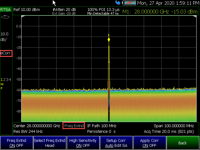
FieldFox preferences are settings that survive a shut down. When your FieldFox is turned OFF, then back ON, these settings remain. All preference settings can be restored to their factory defaults. Learn how in “Save and Reset Preferences” on page 872.
There are two ways to make FieldFox preference settings:
—From softkey selections throughout the FieldFox menu structure. Do this to temporarily try a setting, then press Save Current Preferences. Learn how in the next section.
—From the Quick Settings table.
—Also, refer to: “Audio (Volume) Control” on page 859 and “Display (Settings)” on page 859.
All preferences can be set from the Quick Settings table. They are immediately saved as Preferences when Done is pressed.
How to view and change Preference Quick Settings
1.Press System 7 > Preferences > Preferences
2.Press Next Page and Previous Page to view all settings.
3.To change a setting:
a.Use the arrows () to highlight a setting.
b.Then press Edit. The current setting changes to yellow.
c.Some settings require you to press a softkey to change the value. Otherwise, use the numeric keypad, arrows ( ), or rotary knob to change the value.
d.When finished changing a value, press Done Edit.
4.When finished changing ALL preferences, press Done. All changes are immediately saved as Preferences.
5.To exit the editing session without saving changes, press Esc at any time.
Learn more about these preference settings:
Settings |
|---|
“Save and Reset Preferences” on page 872 (Part of Preferences Softkey Menu) |
—“Language” on page 872 (Similar features as Language in the Preferences softkey menu). —See also, “How to select a Language” on page 873. |
“Audio (Volume) Control” on page 859 and “Audio” on page 876 |
“Alpha Numeric Editing” on page 879 (i.e., ABC/Qwerty keyboard styles) |
“Discrete Colors Softkey Menu” on page 884 - Part of Preferences softkey menu. |
All preference settings can be made at one time from the Quick Settings table.
All settings that can be saved as preferences (except Battery Saver and Startup Mode) can also be made from individual softkey selections throughout the FieldFox menu structure. However, they remain through a FieldFox shut down ONLY when the current settings are saved as preferences.
The table above shows a list of all of these settings and where they are discussed in this User’s Guide.
How to save current settings as Preferences
1.Using softkeys, configure the settings as you would like them to remain.
2.Press System 7 > Preferences
3.Then Save Current Settings There is a beep when your settings have been saved.
4.Press Reset Preferences to restore the factory default settings.
Choose the language in which to display FieldFox softkeys and other messages. Select Save Current Settings to set this language as a preference.
—Press System 7 > Preferences > Language
See also, “How to select a Language” on page 873.
Choose the Global Settings values (Language, Battery Saver, and Startup Mode). See also “Quick Settings Table” on page 870.
How to select Global Settings:
1.Press System 7 > Preferences > Preferences
2.Then use arrow softkeys () or the knob to select Global Settings
3.Then Edit for each of the following:
—Language (see)
—Batter Save Mode (see)
—On
—Off (default)
—Startup Mode (see)
4.Then Done Edit (for each change in setting)
1.Press System 7 > Preferences > Language OR
This setting is available under Global Settings by:
Press System 7 > Preferences > Preferences
2.Then choose from the following:
—English
—Espanol – Spanish
—Deutsch – German
—Italiano – Italian
—Francais – French
—Russian
—Japanese
—Chinese
—Turkish
When the battery saver is OFF, the RF source power is left ON at the end of the sweep which consumes more battery power. This feature is used in CAT, NA, VVM modes, and SA mode when the internal source is turned ON.
Battery Saver is the ONLY FieldFox setting that must be made as a Preference from the Quick Settings table. This setting remains until you change it again.
The FieldFox internal temps will run 2°C – 5°C cooler with the Battery Saver on (the temperature range is dependent on the ambient temp). |
How to set Battery Saver
1.Press System 7 > Preferences > Preferences
2.Then scroll to Global Settings > Battery Saver
—ON – To conserve battery power, the RF source power is turned OFF at the end of each CAT, NA, and VVM mode sweep. This behavior does not impact FieldFox measurements.
—OFF – Source power is kept ON at all times, including during trigger Hold mode and between single sweep acquisitions. The RF source stays at the stop frequency until another sweep begins. This provides a constant, uninterrupted RF output from the RF OUT port. This behavior also provides the highest trace stability sweep-to-sweep which may only be evident while using either single sweep or Run/Hold. With Battery Saver OFF, the use of a full battery charge is reduced by approximately 45 minutes.
The Startup Mode setting determines the mode that becomes active (visible) when User Preset is set to OFF (Factory Preset) and the FieldFox is powered ON. See “User Preset” on page 858.
How to setup Startup Mode
1.Press System 7 > Preferences > Preferences
2.Then scroll to Global Settings > Startup Mode and press Edit.
3.Then repeatedly press the Startup Mode to scroll through the available choices.
—<Default> is the factory default mode for your FieldFox model.
—Built-in Power Meter Mode is NOT allowed as a Startup Mode.
The Startup Option setting determines the behavior of the FieldFox after a restart.
—If the Startup Option is set to Last Power Off State the mode that the FieldFox was set to before a reboot is displayed on power up.
—When the Startup Option is set to User (See Startup Mode), (Default) the Startup Mode selected is the first mode visible on startup and is Option dependent. If User Preset is set to ON, it is loaded on power up.
See “User Preset” on page 858.
How to setup Startup Option
1.Press System 7 > Preferences > Preferences
2.Then scroll to Global Settings > Startup Option and press Edit.
3.Then repeatedly press the Startup Option to toggle through the available choices.
—User (See Startup Mode) or
—Last Power Off State
Display
Choose the Display values (Display Colors, Trace Width, Brightness, Title Enabled, Title). See “Display (Settings)” on page 859.
How to select Display values:
1.Press System 7 > Preferences > Preferences
2.Then use arrow softkeys () or the knob to select Display
3.Then Edit for each of the following:
—Display Colors
—Indoor (default)
—Night Vision
—Outdoor Sun
—Outdoor Dusk
—Outdoor Clouds
4.Trace Width
—Normal (default)
—Wide
Setting trace width to Wide, will result in slower trace refresh rates. |
5.Brightness
—0 to 100% (80% default)
6.Title Enabled
—On
—Off (default)
7.Title
—User Title (default)
8.Then Done Edit (for each change in setting)
Choose the Audio values (Mute, Volume). See also “Audio (Volume) Control” on page 859.
How to select Audio values:
1.Press System 7 > Preferences > Preferences
2.Then use arrow softkeys () or the knob to select Audio
3.Then Edit for each of the following:
—Mute
—On
—Off (default)
4.Volume
—0 to 100 (default is 50)
5.Then Done Edit (for each change in setting)
Choose the Date and Time values (Date and Time, Time Format, Date Format, and Time Zone). See also “Date and Time, Format, and Time Zone Settings” on page 893.
How to select Date and Time units:
1.Press System 7 > Preferences > Preferences
2.Then use arrow softkeys () or the knob to select Date and Time.
3.Then Edit for each of the following:
—Date and Time
—Edit as needed (Refer to “Date and Time, Format, and Time Zone Settings” on page 893):
——Time Format
——Date Format
——Time Zone
4.Then Done Edit (for each change in setting)
Choose the GPS values (GPS State, Elevation Unit, GPS Sync Clock, Display, Lat/Lon Format). See also “GNSS (GPS+) and GPS” on page 886.
How to select GPS distance units:
1.Press System 7 > Preferences > Preferences
2.Then use arrow softkeys () or the knob to select GPS.
3.Then Edit for each of the following:
—GPS State
—Off (default)
—Internal
—External
—Elevation Unit
—Meters (default)
—Feet
—Inches
—GPS Sync Lock
—Off (default)
—Internal
—External
—Display
—On
—Off
—Lat/Lon Format
—dddº mm’ ss.sss”
—ddd.dddddddº
—dddº mm.mmmmm’
—Brit. Natl. Grid
—Then Done Edit (for each change in setting)
When Internal or External is selected, a search is made for satellites overhead. GPS (default) works best when outdoors and in full view of the open sky.
See also, “GNSS (GPS+) and GPS” on page 886.
How to set the frequency reference settings:
This procedure saves your frequency reference settings using the Quick Settings Table in Preferences. Learn more in “Quick Settings Table” on page 870.
1.Press System 7 > Preferences > Preferences then
2.Press Next Page until Frequency Reference is displayed.
3.Use arrow keys or knob to scroll down to until Frequency Ref Source is highlighted.
4.Press Edit > Frequency Ref Sou [GPS] then
5.Choose from the following:
—GPS - (default setting).
—External - Enable GPS using an external, customer-supplied, USB dongle device. A check is made to detect a USB GPS device at the USB connectors.
—Internal - Enable GPS using Option 307 – Built-in GPS. Connect a GPS antenna to the top-panel GPS connector. Learn more about additional GPS antenna accessories at http://www.keysight.com/find/fieldfox. Internal is set automatically when Frequency Reference Source is set to GPS. Learn more in “Frequency Reference Source” on page 890.
When enabled, FieldFox uses the last selected Device and Folder location as the default device location after instrument power cycle.
| Before setting the preferences for the File Folders, you must select the Device and Folder locations. Refer to Chapter 33, “File Management.” |
How to set File Folders
1.Press System 7 > Preferences > Preferences
2.Then scroll to User Folder Persist:
—User Folder Persist (On/Off) – Defaults to the current Device and folder location at power up. Toggle User Folder Persist On/Off when a new Device location is selected location.
—User Folder – displays the default folder location.
—User Device – displays the default device location.
See also: “Alpha Numeric Editing” and “File Saving Naming Options”.
—Keyboard Style – Toggles through Qwerty/ABC style keyboards that the Labeler displays. Refer to “How to use the FieldFox labeler ” on page 916.
—Prefix – Displays the current choice for Prefix. Choices are User, Last File (default), or Off. Refer to Prefixes and Suffixes for Filenames in “Prefixes and Suffixes for Filenames” on page 940.
—Auto Append – Displays the current choice for Auto Append to a filename (Suffix). Choices are Off (default), Number, Date. Refer to “Prefixes and Suffixes for Filenames” on page 940.
Enables/disables the Quick Save feature. Quick Save saves any files you have set to On in the Group Save File Types preferences. Refer to “Group Save File Types Editing” on page 880.
To save the User Device storage location, refer to Chapter 33, “File Management.”
IMPORTANT! To avoid losing data, before using the Quick Save feature, verify that you have all of the correct data file types enabled for saving. |
1.Press System 7 > Preferences > Preferences then
2.Press Next Page until is displayed.
3.Use arrow keys or knob to scroll down to until your choice is highlighted then choose one or more of the following:
—Save/Recall Long Press – Enables/Disables the Quick Save feature. When enabled (default == On) and then hold down the Save/Recall 9 hardkey for >600 ms, the specified files are saved to a file with the FFoxData prefix. See also, Quick Save Show File Dialog below and “Prefixes and Suffixes for Filenames” on page 940.
—Quick Save Prefix – Chooses the name of the Quick Save data file’s prefix. Press the Edit softkey to edit the prefix name in the “Quick Save Prefix” menu (default == FFoxData). Refer to “Prefixes and Suffixes for Filenames” on page 940.
—Quick Save Suffix – Chooses the name of the Quick Save data file’s suffix. Press the Edit softkey to edit the suffix type Number or Data (default == Date). Refer to “Prefixes and Suffixes for Filenames” on page 940.
—Quick Save Show File Dialog – When the Quick Save Show File Dialog is set to On (default == Off), pressing Save /Recall 9 for >600 ms causes the FieldFox Labeler to open and displays the current filename that is going to be used or can be edited to save your data. Learn more, see “Prefixes and Suffixes for Filenames” on page 940 and to “Group Save File Types Editing” on page 880.
Enables/disables the selected file types to be saved as part of the Group Save File Types feature. (Default for all group save file types = Off.) Refer to “Quick Save Editing” on page 879.
Group Save File Types Procedure
1.Press System 7 > Preferences > Preferences OR
Press Save/Recall 9 > More > Preferences then
2.Press Next Page until Group Save File Types is displayed.
3.Use arrow keys or knob to scroll down to until your choice is highlighted then:
4.Press Edit then
5.Press ’file type’ Data (.xxx) to enable/disable the data file type (default = Off). (e.g., Image (.png) ON OFF, CSV Data (.csv) ON OFF, etcetera).
6.Repeat steps 3 through 5 as required.
7.Press Done Edit to exit the current data type softkey menu.
8.Press Done to exit the Preferences menu and save your Preferences.
Group Save File Types
—State+Trace (.sta) – Enables/Disables .sta as a group. file to be saved when the Quick Save (Save/Recall 9) hardkey is pressed for ~3 seconds.
—State (.sta) – Enables/disables .sta files as a group file to be saved when the Quick Save (Save/Recall 9) hardkey is pressed for ~3 seconds.
—Image (.png) – Enables/disables .png files as a group file to be saved when the Quick Save (Save/Recall 9) hardkey is pressed for ~3 seconds.
—CSV Data (.png) – Enables/disables .csv data files as a part of the group files to be saved when the Quick Save (Save/Recall 9) hardkey is pressed for ~3 seconds.
—S1P Data (.s1p) – Enables/disables .s1p data files as a part of the group files to be saved when the Quick Save (Save/Recall 9) hardkey is pressed for ~3 seconds.
—S2P Data (.s2p) – Enables/disables .s2p data files as a part of the group files to be saved when the Quick Save (Save/Recall 9) hardkey is pressed for ~3 seconds.
—Matalab Data (.mat) – Enables/disables .mat data files as a part of the group files to be saved when the Quick Save (Save/Recall 9) hardkey is pressed for ~3 seconds.
—SDF Data (.sdf) – Enables/disables .sdf data files as a part of the group files to be saved when the Quick Save (Save/Recall 9) hardkey is pressed for ~3 seconds.
Choose the CAT distance units (i.e., Meters (default), Feet, Inches). See “DTF Units” on page 78.
How to select CAT distance units:
1.Press System 7 > Preferences > Preferences
2.Then Edit for each of the following:
—Distance Units:
—Meters (default)
—Feet
—Inches
—TDR Sweep:
—Cable (default and the most accurate)
—Auto
3.Then Done Edit (after each change in setting)
Choose the CAT/NA settings for SnP file save, default factory error corrections, extended cal default. See also “> What Data Processing functions are included in saved SNP Data:” on page 922.
How to select CAT/NA defaults:
1.Press System 7 > Preferences > Preferences
2.Then use arrow softkeys or the knob to select CAT/NA
3.Then Edit for each of the following:
—SnP File Save
—Default
—Advanced
4.Then Done Edit (after each change in setting)
Choose the SA setting for Individual measurement Control default. See also “Alignments” on page 219.
How to select SA defaults:
1.Press System 7 > Preferences > Preferences > Next Page until the SA setting is visible.
2.Then use arrow softkeys or the knob to select the SA Setting.
3.Then Edit for each of the following:
—Individual measurement Control
—On (Default - recommended)
—Off
—ADC Over Range Warn Emphasis
—None (Default) no added emphasis to the ADC Over Range warning on the screen.
—Big Font + Beep – this option makes the ADC Over Range warning have a larger text which is accompanied by a Beeping sound to alert you of the ADC Over Range.
—Beep – this option keeps the default text size, but alerts you of an ADC Over Range with a Beeping sound.
—Big Font – this option makes the ADC Over Range warning have a larger text, no sound with this option.
—Beep Length (RTSA and SA Modes Only)
When ADC Over Range Warn Emphasis is set to either, Big Font + Beep or Beep, the FieldFox audible beep sounds whenever an ADC Over Range error occurs.
You can adjust the Beep Length from 500 ms (default /minimum) up to 2 seconds. There is always a gap of at least 1s between audible beeps.
To set the Beep Length: Highlight the Beep Length setting then, press Edit > 2s (i.e., in this example, to set the audible beep to be on for 2 seconds).
4.Then Done Edit (after changing setting)
The discrete colors softkey menu can be used to increase the choice of colors displayed from two to up to six colors, for easier measurement readings. Refer to Figure 31-7.
Figure 31-7 Display Example: Color Coded Bar Scale (x6 Colors)
Using the Discrete Colors Softkey Menu
1.Press System 7 > Preferences > Discrete Colors
2.Choose from the following:
—Discrete Colors ON OFF – to enable/disable the discrete colors greater than 2.
—Number of Colors – choose up to 6 discrete colors (Minimum (default) = 2, red and blue).
—High Power Red Blue – choose red or blue to choose the color to indicate the highest power levels (default = Red).
Options (Licensing)
You can view and install options on your FieldFox. To see a comprehensive list of the options that are available, view the Configuration Guide at: https://www.keysight.com/us/en/assets/3125-1447/configuration-guides/FieldFox-Handheld-Analyzers-D-models.pdf.
How to view the Installed Options
1.Press System 7 > System Configuration > Options (Licensing)
2.Then Show Options
The currently installed options are listed.
How to Install Options (License File)
A license file (*.lic file) must already be on a USB Flash Drive. To learn how to obtain a. license file (*lic file), visit: https://www.keysight.com/us/en/lib/resources/service-manuals/keysight-fieldfox-library-help-and-manuals-2153870.html.
1.Insert the USB Flash Drive in the FieldFox.
2.Press System 7 > System Configuration > Options (Licensing)
3.Then Install Options The FieldFox reads, validates, then installs the options.
4.Press and hold the power button to shut down, then restart the FieldFox.
How to Delete ALL Options
Deleting individual options is NOT supported.
1.Press System 7 > System Configuration > Options (Licensing) > Advanced
2.Then Delete All Options
After a warning message, all options on the FieldFox are deleted.
IMPORTANT! Delete All CFG Options is to be used by Service Personnel ONLY. |
For more information about Licensing, see the FieldFox Service Manual at: https://edadocs.software.keysight.com/kkbopen/fieldfox-manuals-firmware-software-and-product-support-589310103.html.
GNSS (GPS+) and GPS IMPORTANT! The FieldFox may display "Ant OPEN", even when a GPS antenna is connected to the FieldFox. If the GPS antenna is powered by another power supply and has a DC blocking capacitor where the feed is connected to FieldFox, then minimal amounts of current will be drawn from the FieldFox, so the instrument will display "Ant OPEN". The threshold to detect the presence of an antenna is approximately 1.6 mA.
GPS (Global Positioning System) allows you to ‘stamp’ each data trace with your physical position in latitude/longitude/elevation format. This can be useful when making measurements on cell towers or other antennas at remote locations.
—With Option 307, GPS is available with the built-in receiver accessed through the top-panel SMA (f) connector. This connector has a settable 3.3 VDC or 5 VDC bias voltage which is switched ON when GPS is set to Internal. This system is designed for use with an active antenna such as the Keysight N9910X-825.
—Without Option 307, GPS is usable ONLY with an external GPS receiver that is shipped with Microsoft “Streets and Trips” and “AutoRoute”. The GPS receiver is NOT available from Keysight. Only the GPS USB receiver is used with the FieldFox. Therefore, it is NOT necessary to purchase the very latest version of the map software.
GPS settings are the same with, or without, Option 307.
Your GPS settings can be saved with Preferences. Learn more in “Quick Settings Table” on page 870.
1.Press System 7 > System Configuration > GPS
2.Then choose from the following:
3.Display ON OFF Enable and disable the GPS display on the FieldFox main window.
4.GPS then choose from:
—OFF - Disable GPS (default setting).
—External - Enable GPS using an external, customer-supplied, USB dongle device. A check is made to detect a USB GPS device at the USB connectors.
—Internal - Enable GPS using Option 307 – Built-in GPS. Connect a GPS antenna to the top-panel GPS connector. Learn more about additional GPS antenna accessories at http://www.keysight.com/find/fieldfox. Internal is set automatically when Frequency Reference Source is set to GPS. Learn more in “Frequency Reference Source” on page 890.
When Internal or External is selected, a search is made for satellites overhead. GPS works best when outdoors and in full view of the open sky. When several satellites are found, the following screen appears (when Display is set to ON) and is updated frequently:
| As the bar graph count exceeds 9 bars, the “dB” text is dropped from the number displayed on the bar. Units for C/No are dBHz. |
Figure 31-8 GPS Display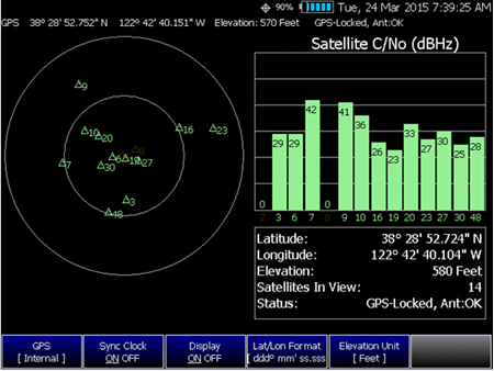
—The left portion of the screen displays satellites and the corresponding number on the adjacent Satellite Power chart.
—The right portion of the screen displays Satellite Power Carrier to Noise (C/No) dBHz values on the tops of the satellite power chart.
| The C/No values returned are not calibrated at the factory or warranted for accuracy. The numbers retrieved are passed unprocessed directly from the GPS receiver in use. |
GPS Status
With GPS enabled the following is displayed at the top of the FieldFox screen:
The following icons (located in RED circle above) indicate the GPS lock status:
 - GPS ON and locked on satellites.
 - GPS ON, but NOT locked on satellites.
 - GPS ON, but no GPS receiver is present or detected.
The following annotation (BLUE circle in above image) indicates the INTERNAL, top-panel antenna status:
—Ant: INIT – antenna status initializing.
—Ant: OK – antenna present and working.
—Ant: OPEN – antenna is not drawing DC bias current. This could occur when an active antenna is not connected properly or the antenna does not require DC bias current. Antennas that do not require bias current can still provide an accurate GPS reading.
—Ant: SHORT – antenna center pin has been shorted to ground. The internal bias circuitry is disabled for about one minute, then re-enabled. You can also press GPS OFF, then GPS Internal to quickly re-enable the antenna bias.
See also, “GNSS and GPS Freq Ref Source Settings” on page 890.
1.Press System 7 > System Configuration
2.Then GNSS (GPS+) or GPS (depending on options) > GNSS Settings
3.Then choose from the following:
—Enable and disable the synchronization of the FieldFox internal clock to the GPS UTC time standard.
The GPS Sync setting has the same restrictions as the Date and Time setting. Learn more in “Date and Time” on page 876. |
—ON The FieldFox clock is synchronized and updated approximately once every hour to the time of the GPS clock.
—OFF The FieldFox clock is NOT synchronized with GPS. When set to OFF after Sync was ON, the date and time does NOT revert back to the settings before the clock was synchronized.
—Display ON OFF Enables or disables displaying Lat/Lon Format and Elevation Units.
—Lat/Lon Format Change th format of the GPS display on the FieldFox screen. Choose from:
—ddd°mm’ ss.sss” degrees, minutes, seconds (default setting)
—ddd°mm.mmmmm’ degrees, minutes, fractional minutes
—ddd.ddddddd° decimal degrees
—None Lat/Lon is not displayed.
—Elevation Unit Choose from:
—m (Meters)
—Feet
—Inches
—Antenna Voltage Choose from:
—3.3V 5V – Settable to: 3.5 VDC or 5 VDC. When the bias voltage is set to ON and when the GPS is set to Internal. This system was designed for an active antenna such as the Keysight N9910X-825
Saving Data with GPS Enabled
GPS position and clock data are included when data is saved with the following files types: *.csv, *.SnP, State, State+Trace data save.
A warning is shown if the GPS is ON but unlocked at time of save, or if the GPS feature is ON but no GPS is physically present at time of save.
The following is a sample S1P file with GPS information:
!GPS Latitude: 38 28.87717 N
!GPS Longitude: 122 42.66625 W
!GPS TimeStamp: 06/25/2010 16:24:48
!GPS Seconds Since Last Read: 2s
Saving GPS Display Data
To save the current GPS data displayed:
1.Press Save/Recall 9
2.Then Save File Picture (PNG)
A menu opens to enable naming the file you are saving (*.png).
More GNSS Settings
1.Press System 7 > System Configuration > GNSS Selection
2.Then choose from the following:
—GPS Refer to “How to make GPS settings” on page 886.
—GLONASS Global navigation system, operating as part of a radio navigation-satellite system. Learn more “More GNSS and GPS settings” on page 888.
—BDS - China’s BeiDou navigation system. Learn more “More GNSS and GPS settings” on page 888.
—GALILEO - European navigation system. Learn more “More GNSS and GPS settings” on page 888.
GNSS and GPS Freq Ref Source Settings
For convenience, the GNSS Settings menu includes the Freq Ref Source softkey.
1.Press System > System Configuration > GNSS (GPS+) > Freq Ref Source [GPS] then
2.Choose one of the following:
—Int, Ext, or GPS
For more, on the Freq Ref Source softkey choices, refer to “Frequency Reference Source” on page 890.
The FieldFox internal frequency reference source is used to make accurate and stable measurements. To improve measurement accuracy and stability, you can use a highly-stable external 10 MHz reference source or a precision timing signal provided with Built-in GPS (Opt. 307).
The Frequency Reference setting will survive a Factory Preset or Mode Preset and is saved as part of the Instrument State. When resuming after Standby, the FieldFox will display an Unlock message while it acquires a lock to an external or GPS source.
How to select Frequency Reference Source
1.Press System 7 > System Configuration > Frequency Ref > Freq Ref Source then
2.Then choose from the following:
—Int Internal frequency reference.
—Ext External frequency reference. Connect the 10 MHz External Reference to the Ref In/Trig In SMA (f) connector on the FieldFox top panel. The FieldFox may take up to 10 seconds to lock to a valid External Reference source.
—GPS Available ONLY with Built-in GPS (Opt. 307). When selected, the internal GPS is immediately enabled and a search for satellites begins. When satellites are found, the precision timing signal is NOT used directly, but is used to correct the absolute frequency of the internal reference many times per second.
Hold-over mode
When the GPS signal is lost, the last GPS reading is used as a hold-over correction value for the internal reference. The hold-over correction value is no longer used, but instead the factory-set correction value is used, when any of the following occur:
—when GPS is disabled.
—when Reference Source is set to Internal.
—when the FieldFox resumes from Standby mode or shut down.
Frequency Reference Status
When switched to Ext or GPS, one of the following annotations appears in the lower-left corner of the screen:
—EXT R – External reference is selected.
—GPS R – GPS reference is selected.
—GPS H – Internal Reference is used with last ‘hold-over’ correction reading.
If the FieldFox does NOT find an appropriate Ext or GPS reference signal, then Ext Ref UNLOCKED is displayed in the lower-left corner of the graticule area. This can occur when any of the following conditions exist:
—NO reference signal is present.
—A low or very high-level external reference signal is present. For best results, the signal should be between –5 dBm and +5 dBm.
—The external reference is off-frequency.
To learn the expected measurement accuracy when connected to a frequency reference source, see the FieldFox specifications in Appendix B: “Specifications/Data Sheet”.
Reference OUT
The internal 10 MHz frequency reference is available from the Ref/Trig output connector on the right-side panel. Use this signal as a common frequency reference when making measurements using external equipment. See this connector in “Top Panel” on page 47.
Variable Voltage Source (Opt. 309)
An internal DC source, available with Opt. 309, may be used to provide power for external devices. The maximum power available is 8 watts.
The voltage is output through an SMB (m) output connector located on the left-side panel. See the connector in “Left Side Panel” on page 50.
An optional SMB (f) to BNC (m) bias-tee power cable is available with Keysight part number: N9910X-713.
The following status line is provided near the top of the FieldFox screen.
Figure 31-9 Voltage Source Status Line 1.Voltage source state: ON, OFF, TRIPPED. 2.Voltage setting from 1.00 V to 32.00 V with.01 V resolution. 3.Current: The amount of current (in Amperes) being drawn from the source. 4. Max Current: A conservative estimate of maximum current possible given the present voltage setting. The actual ‘trip’ level may be slightly different. 
How to make Voltage Source settings
1.Press System 7 > System Configuration > Voltage Source
2.Then Source ON OFF to enable and disable the voltage source output.
Then choose:
—Then Voltage x.xx V Using arrows, the rotary knob, or numeric keypad, enter a value between 0.001 and 32 volts.
—Clear Overload If the voltage source becomes ‘TRIPPED’ press to re-enable the voltage source output. Then set Source ON.
—Status Line ON OFF Turn ON and OFF the voltage source status line that appears near the top of the screen. The status line is always ON while making Voltage Source settings.
—Hi Impd. Load ON OFF Enables/Disables low current use (Step) and high current use (Ramp). Default = OFF (Low current (Step)).
For security reasons, you can prevent frequency information from appearing on the FieldFox while in SA, NA, or CAT modes.
How to set Security Level
1.Press System 7 > System Configuration > Security Level
2.Then choose from the following:
—None All frequency settings are visible.
—High Frequency information is blanked from the following:
—Display annotation
—Softkeys
—Marker display and marker table
—Calibration properties
—All settings tables
—Limit line tables
—All saved .png files
—Any of the following will re-display frequency information:
—Set to None, Preset, Mode Preset, or FieldFox restart.
Date and Time, Format, and Time Zone Settings
Set the local date and time, Date and Time format, and Time Zone that is shown on the FieldFox screen. The Date and Time is also used to identify files that are saved.
The Date and Time can also be set by synchronizing with GPS satellites. Learn more in “GPS – Distance Settings” on page 877.
How to Update Date and Time using Internet
This method of setting the Date and Time does NOT have the security restrictions of the other methods (listed below).
This method will NOT set the correct Time Zone. You must do that using the manual method. See below.
1.Press System 7 > System Configuration > More > Update Time using Internet
2.Connect a LAN cable that is also connected to the Internet.
3.Then press Update Time using Internet. When successful, a message is displayed indicating the amount of time correction that occurred.
—Optional: Set the following when a Proxy server is used to connect to the internet:
—Proxy Host – Enter the name of the proxy host.
—Proxy Port – Enter the port number of the proxy host.
How to MANUALLY set Date and Time, Format, and Time Zone
| Because of licensing security, the manual and GPS Sync methods to set Date and Time are restricted as follows: – Can be set backward no more than 5 hours at a time. – Can be set forward any amount of time. – Can be set backward or forward no more than once in a day. A new day begins at midnight. – There is no restriction for setting the Time Zone. – To change the Date and Time backward a significant amount, send an email to csg.servicedesk@keysight.com. |
| BEFORE manually setting the Date and Time, be absolutely certain that the Time Zone setting is correct. |
1.Press System 7 > System Configuration > More > Date and Time.
2.Press the arrows to highlight the row to be edited.
3.Then press Edit.
4.Use the arrows or rotary knob to select and to edit a field.
5.Press Cancel or Done when the edits are complete.
6.Press Done to exit the Date and Time settings. The readout in the upper-right corner of the FieldFox screen will update accordingly.
Configure the 1G LAN settings to be used to communicate with the Data Link Software and connect to the FieldFox for remote SCPI operation. Learn more about Data Link at: www.keysight.com/find/fieldfoxsupport.
The 1G LAN port interface (lan0) also supports IQ Streaming with a maximum gapless span of 5 MHz.
Figure 31-10 Table 31-1 LAN LEDs LAN LEDs When FieldFox is connected to the LAN, the flashing LAN LEDs have the following definitions: Green: Flashing indicates packets are being transferred. Yellow: —Flash, pause = 10 Mbit link speed —Flash, flash, pause = 100 Mbit link speed —Flash, flash, flash, pause = 1 GBit link speed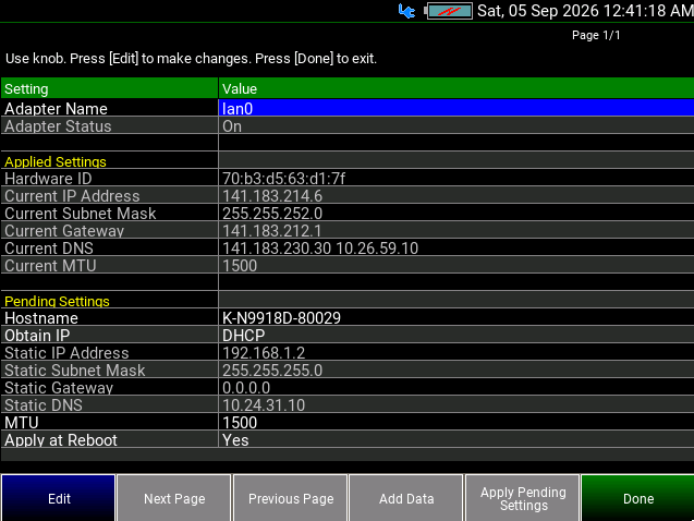
How to configure 1 G LAN settings
The grayed out fields settings can NOT be edited.
1.Press System 7 > System Configuration > More > Network Config.
2.Then choose from the following:
—Use the arrows to select one of the following, then press Edit.
—Adapter Name Selects the Ethernet adapter to configure. Choose from.
—lan0 - Standard 1 G Ethernet LAN interface selected.
—lan1 - Optional 10 G Ethernet (SFP+) interface used for high-speed IQ Streaming available when a valid 10 G SFP+ module is inserted into the SFP0 port.
—Adapter Status Turns on the selected network adapter. Choose from:
—On - Enable lan0 adapter. This will not be allowed if Secondary Max Protect State is in effect.
—Off - Disable lan0 adapter.
—Hostname Change the name that can be used to address the FieldFox if your server supports this feature. The default hostname is generated automatically.
—Obtain IP Choose from:
—DHCP - IP Address is assigned dynamically. If your server supports this feature, the IP Address for the FieldFox is assigned each time it is started. All the Static Network Settings will be disabled.
—Static - Set the IP Address manually. The Address remains until you change it. Continue for other Static Network Settings.
—Static IP Address - Enter the IP Address – including periods - in the format nnn.nnn.nnn.nnn
—Static Subnet Mask - Enter the Subnet Mask – including periods - in the format nnn.nnn.nnn.nnn
—Static Gateway - Enter the Static Gateway – including periods - in the format nnn.nnn.nnn.nnn
—Static DNS - Enter the Static DNS – including periods - in the format nnn.nnn.nnn.nnn
—MTU - Maximum Transmission Unit setting. Configures the Ethernet packet size for IQ Streaming. Default is 1500 bytes. Larger MTU values (jumbo frames) can improve throughput. Ensure the target computer and network equipment support the selected MTU setting.
| The maximum configurable MTU size for the 1 G (lan0) interface is 9000 bytes. Configure the MTU size to a value supported by the receiving system. |
—Apply at Reboot Choose from:
—Yes The above settings take effect when the FieldFox is rebooted.
—No The above settings take effect immediately.
3.Press Done Edit after editing any Network Configuration setting to save the changes.
4.Press Apply Pending Setting to commit the changes made to the Network Configuration “Pending Settings” section. The values in the “Applied Settings” section list correspond to the current values that the adapter is configured with. If the adapter status is off, all values will be -.-.-.- 
5.Press Done to complete and close the Network Configuration.
The 10 G Ethernet interface (lan1) provides high-speed IQ data transfer for Wideband IQ Streaming on supported D-series models. The interface uses the SFP+ port (SFP0) where the valid 10 G SFP+ module inserted and supports gap-free streaming up to 40 MHz or 120 MHz bandwidth, depending on hardware configuration and selected sample format.
The interface can be configured using DHCP or Static IP addressing from the LAN Configuration menu. For best streaming performance, use a direct connection to the destination host and configure a large MTU size where supported.
Figure 31-11 Table 31-2 SFP LEDs SFP LEDs The LEDs next to the SFP0 port are unlit when there is no LAN connection. When a valid connection is established, the LEDs indicate the following states: Green: —Solid ON = Link established —Flashing = Network traffic activity Yellow: —Solid ON = Link established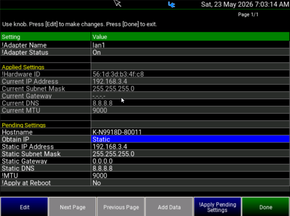
How to configure 10 G Ethernet (SFP+) settings
The grayed out fields settings can NOT be edited.
1.Press System 7 > System Configuration > More > Network Config.
2.Then choose from the following:
—Use the arrows to select one of the following, then press Edit.
—Adapter Name Selects the Ethernet adapter to configure. Choose from.
—lan0 - Standard 1 G Ethernet LAN interface.
—lan1 - Optional 10 G Ethernet (SFP+) interface used for high-speed IQ Streaming available when a valid 10 G SFP+ module is inserted into the SFP0 port.
—Adapter Status Turns on the selected network adapter.
—Up - Enable lan1 adapter. This will not be allowed if Secondary Max Protect State is in effect.
—Off - Disable lan1 adapter. The following 10 G Ethernet (10GbE) SFP+ transceiver modules have been qualified and supported for use with IQ Streaming on the FieldFox: – Finisar FTLX8574D3BCL (10GBASE-SR, multimode fiber) – Finisar FTLX1475D3BCL (10GBASE-LR, single-mode fiber) – FS SFP-10G-T Generic option(10GBASE-T RJ45 copper).
—Hostname Change the name that can be used to address the FieldFox if your server supports this feature. The default hostname is generated automatically.
—Obtain IP Choose from:
—DHCP - IP Address is assigned dynamically. If your server supports this feature, the IP Address for the FieldFox is assigned each time it is started.
—Static - Set the IP Address manually. The Address remains until you change it. Continue for other Static Network Settings. Recommended to use a Static configuration for optimal performance.
—Static IP Address - Enter the IP Address – including periods - in the format nnn.nnn.nnn.nnn
—Static Subnet Mask - Enter the Subnet Mask – including periods - in the format nnn.nnn.nnn.nnn When both the 1 G LAN interface and the 10 G Ethernet (SFP+) interface are enabled, configure each interface with a different subnet. This allows the FieldFox to automatically route IQ Streaming traffic to the appropriate network adapter based on the destination host IP address and helps prevent network routing conflicts..
—Static Gateway - Enter the Static Gateway – including periods - in the format nnn.nnn.nnn.nnn If a gateway is not required, set Static Gateway to 0.0.0.0. This prevents the FieldFox from attempting to communicate with a non-existent gateway, which may affect network performance.
—Static DNS - Enter the Static DNS – including periods - in the format nnn.nnn.nnn.nnn
—MTU - Maximum Transmission Unit setting. Configures the Ethernet packet size for IQ Streaming. Default is 1500 bytes. Larger MTU values (jumbo frames) can improve throughput. Ensure the target computer and network equipment support the selected MTU setting. The maximum configurable MTU size for the 10 G Ethernet (SFP+) interface is 16000 bytes. For Enhanced IQ Streaming, the maximum supported MTU size is 9000 bytes. Configure the MTU size to a value supported by the receiving system.
Selecting an MTU size larger than that supported by the receiving system may affect streaming performance.
—Apply at Reboot Choose from:
—Yes The above settings take effect when the FieldFox is rebooted.
—No The above settings take effect immediately.
3.Press Done Edit after editing any Network Configuration setting to save the changes.
4.Press Apply Pending Setting to commit the changes made to the Network Configuration "Pending Settings" section. The values in the "Applied Settings" section list correspond to the current values that the adapter is configured with. If the adapter status is off, all values will be -.-.-.-
5.Press Done to complete and close the Network Configuration.
When the FieldFox is without a power source, this setting allows the FieldFox to power ON automatically when the DC Adapter is inserted or Battery is installed without pressing the power button.
| For this feature (Auto Power ON) to function properly, the battery must not be installed initially. |
How to set Power ON automatically
1.Press System 7 > System Configuration > More > Power-On Trig
2.Then choose from the following:
—OFF The FieldFox will power ON only when the power button is pressed.
—Ext DC The FieldFox will power ON automatically when the DC Adapter is inserted.
—Battery The FieldFox will power ON automatically when battery is installed.
—Any The FieldFox will power ON automatically either DC Adapter is inserted or battery is installed.
The FieldFox Package Installer enables you to download new versions of firmware from either a USB memory or SD Card. Additionally, the Utility softkey enables you to backup user files or restore user files.
How to run the Installer Before running the Installer to update your firmware, you might want to back up your user data. Refer to “How to restore files” on page 902.
1.Press System 7 > System Configuration > More > Firmware Update > Start Installer.
The Installer software opens after a couple of seconds. If no files are displayed, verify that a USB memory or SD Card is installed and press Refresh List.
2.Then chose from the following:
—Then the arrows or the knob to scroll to the firmware you want to install.
3.Press Start Install and the following occur:
“Current Step Progress:” bar and a “Total Progress:” bar are displayed along with this message: “Copying package. Do not remove install media.”
When the installation is completed, the FieldFox reboots.
This procedure backs up your user data to a USB or SD card. See also “How to restore files” on page 902. If you backup multiple versions of the user files, the FieldFox appends a “_#” to each subsequently stored file. During restore, the file with the highest appended number is loaded into the FieldFox.
From the initial Installer menu:
1.Press Utility > Backup Data
A message is displayed: “Choose backup file location.”
2.Then choose either SD Card or USB
A progress bar and a message is displayed: “Saving user data…”
3.Press Cancel to exit without backing up your files and returning to the initial Installer menu.
This procedure restores user files from a USB or SD card. See also “How to backup files” on page 902. Restoring files overwrites the existing user data on the FieldFox. If you backup multiple versions of the user files, the FieldFox appends a “_#” to each subsequently stored file. During restore, the file with the highest appended number is loaded into the FieldFox
If your stored any user files to a USB or SD card, this procedure restores those files.
From the initial Installer menu:
—Press Utility
—Then Cancel to exit without restoring your files and returning to the initial Installer menu.
Or
Press Restore Data
—A message is displayed: “This option will COMPLETELY ERASE existing user data. ARE YOU SURE?”
—Then No to return to the previous menu without restoring files.
Or
Press Yes
—Then choose either SD Card or USB
A progress bar and a message is displayed: “Restoring user data…”
Service Diagnostics When the FieldFox is powering up, the firmware does a very high level verification of the hardware components. This high level verification does not involve applying any power to any of the internal hardware components. The FieldFox will generate an error message, if the hardware fails the verification. To learn more, refer to the FieldFox Programming Help and to the Service Guide for your FieldFox.
—The Service diagnostics menu is generally used to display service-related information. To access these menu items, press System 7 then Service Diagnostics.
—Model Number – FieldFox model
—Serial Number – Identification number of your FieldFox
—Firmware Release – The currently installed version of software. Check to see if you have the latest firmware at: www.keysight.com/find/fieldfoxsupport
—Network Identity – The network name and current IP address of your FieldFox.
—Reflectometer Factory Cal - The Factory (CalReady) Calibration shows the date and time that the factory cal was performed for each test port and the Thru connection. The format is P1 <date time>, P2 <date time>, P1-P2 <date time>. The factory calibration is updated when you send your FieldFox to Keysight for Instrument Calibration. Learn more in Appendix C: “Instrument Calibration”.
The Event Log shows the information that has appeared on the FieldFox screen. The most recent information is at the top of the table.
Press Clear Events to erase this information.
Battery
Learn more in Chapter 34,“Working with the Lithium-Ion Battery”, on page 945945.
Internal Temperatures
Learn about the importance of the internal FieldFox temperatures in “FieldFox High Temperature Protection” on page 35.
Power Monitor
For more information about FieldFox power management, see “Power Management Monitor” on page 41.
Erase User Data IMPORTANT! The process in this section erases all User Data from the FieldFox. Before proceeding, Keysight strongly recommends that you back up all of your User Data to an external storage device. refer to “How to backup files” on page 902.
All data that you have written to the FieldFox can be erased with the press of a button. You would do this if your FieldFox is located in a secure environment and must be routinely erased of sensitive data.
All data is removed from the FieldFox internal “UserData” partition. This includes all State files and Trace + State files (*.sta), all Data files (*.csv, *.snp), all Picture files (*.png), all Cal Kit files, and all Cable files.
External media that is inserted (mini-SD card or USB flash drive) is NOT erased.
The “Lost Clusters" folder and files are NOT erased because they are part of the file system housekeeping.
How to Erase User Data
1.Press System 7 > Service Diagnostics > Advanced > Erase User Data
2.Then Confirm Erase
—Then the following occurs:
—All data files and folders are deleted from the “UserData” partition.
—The FieldFox is rebooted, which manages the newly-freed data and re-writes the factory cal kits and cable files.
Understanding the Fan Controls
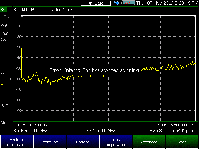
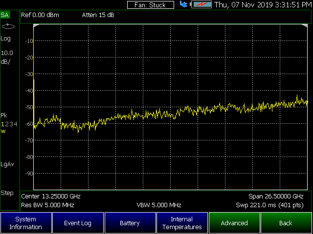
| If the FieldFox displays a “Fan Stuck” or “Error: Internal Fan has stopped spinning”, to avoid incorrect measurements and possibly damaging your FieldFox, shut your FieldFox down and contact Keysight. Refer to “Contacting Keysight” on page 5. The fan is replaceable, but not removable by non-Keysight trained personnel. |
This section contains the following:
—“How to find the Fan Control Softkey Menu”
—“Fan Error Messages” on page 907
How to find the Fan Control Softkey Menu
This section discusses how to locate the fan control softkeys to monitor your fans performance (i.e., the fan control softkeys are for informational purposes only).
1.Press System 7 > Service Diagnostics > Advanced.
2.Then Fan Control
3.These softkeys are for informational purposes only:
—Fan Mode Auto – Manual is not selectable.
—Manual Speed [Medium] – this is the default. No other speeds are selectable.
—Fan RPM – displays the current fan RPM.
—Fan Temp – displays the current fan air temperature.
—Back –to exit the fan control softkey menu.
Figure 31-12 Fan Control Softkeys – Informational Use Only (Not Editable)
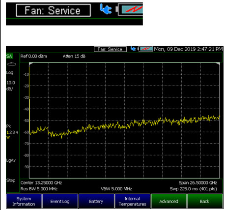
The FieldFox displays fan error messages, when the fan is not functioning properly. Refer to Figure 31-13, Figure 31-14 on page 908, and Figure 31-15 on page 909.
| If the FieldFox displays a “FanStuck” or “Error: Internal Fan has stopped spinning” message, to avoid incorrect measurements and possibly damaging your FieldFox, shut your FieldFox down and contact Keysight. Refer to “Contacting Keysight” on page 5. If the FieldFox displays a “Fan: Service” message the fan needs replacing. Call Keysight and request a fan kit. Refer to Figure 31-15 on page 909 and to “Contacting Keysight” on page 5. |
Figure 31-13 Initial Fan Stuck Error Message – Displays For a Few Seconds