This topic describes the Calibration Wizard Setup window. Click a region on the image to learn more.
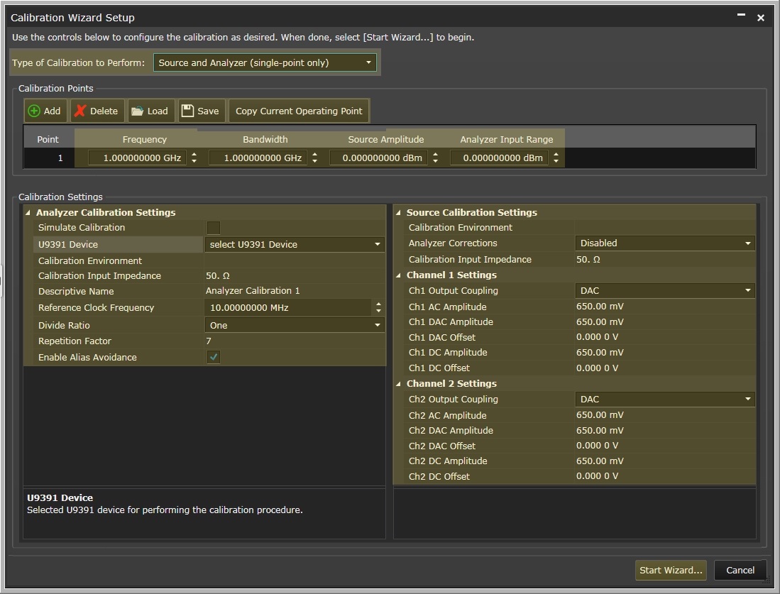
Selects which hardware components in the system you want to calibrate. Choices include the following:
This table defines which points in the spectrum you want to apply corrections. Each point is defined by frequency, bandwidth, source amplitude, and analyzer input range. The editing functions below are only available for multi-point calibrations.
Adds a calibration point (row) to the table.
Removes the selected calibration point (row) from the table.
Opens a file management window where you can select a *.csv file of calibration points to populate the table.
Opens a file management window where you can save the table's calibration points to a *.csv file.
Copies the current calibration point, including frequency, bandwidth, source amplitude, and analyzer input settings from the current system configuration, and pastes them into the selected point in the calibration points table. It is a quick way to populate the table with settings that match your measurement environment. You can make variations to the settings in each point from there.
This area of the Calibration Wizard window contains calibration settings for the hardware. The analyzer settings are on the left side of the window and the source settings are on the right side.
Enables a simulated calibration procedure for use when developing control programs with the programming API. The generated correction data will not be valid for use in measurement processing.
Selected U9391 device for performing the calibration procedure. If there is only one U9391 device connected to the computer, it is selected by default.
The calibration environment includes the factors of temperature, humidity, cable connection, additional fixtures, etc. The name should represent a specific calibration environment. When receiver calibration mode is in “Auto” you can enter the same calibration environment string and the software will only load calibrations with the identical environment. For example, if you were to calibrate the receiver with a 6 dB pad connected at the input to reduce mismatch uncertainty, you can enter the string “with 6 dB pad” in the calibration environment during calibration and during measurement, and only those calibrations will be used.
Desired analyzer input impedance for the analyzer calibration. This is used to interpret the Input Range setting. 50 ohm by default and should not normally be changed.
Name to annotate corrections generated by the analyzer calibration. This is for your reference and doesn’t affect how the calibration data is used.
Frequency of the reference clock applied to the U9391 device. This should always be 10 MHz.
Divide ratio applied to reference clock by U9391 device to determine the pulse repetition frequency (and therefore the calibration tone spacing and calibration tone amplitude). By default, this value is one and the U9391 will generate tones every 10 MHz. For bandwidths greater than 200 MHz, this is the desired setting. For bandwidths below 200 MHz, we use the divider to create more tones. For example, a divide ratio of 2 creates tones every 5 MHz, a divide ratio of 4 creates tones every 2.5 MHz and so on. The goal is to get at least 21 comb teeth in the measurement bandwidth. The table below gives the recommended settings:
| For bandwidths less than or equal to: | Use divide ratio: |
|---|---|
| 20 MHz | 16 |
| 40 MHz | 8 |
| 100 MHz | 4 |
| 200 MHz | 2 |
| otherwise | 1 |
Tuning parameter to optimize calibration procedure between calibration duration (lower values) and variance reduction (higher values). Increasing this value by one doubles the data acquired for a calibration procedure. For example, a repetition factor of 7 increased the data acquisition by a factor of 128 over a repetition factor of 1. The default is 7, and the value should only be increased.
Detects and reconfigures the calibration measurement to avoid calibration signal aliasing. If the requested measurement frequency is found to have significant calibration signal aliasing, there will be a message similar to: “Applied frequency offset (100000 Hz) to avoid calibration tone aliasing.” The intent is that you will save the calibration data and then use it at your desired frequency, knowing that this will introduce small errors (the Auto mode allows frequency offset up to 1 MHz ).
The size of the frequency offset will 10 MHz / divide ratio / 100.
If you do not wish to allow the proposed offset, you have three choices:
Enable Alias Avoidance will double the time required for the calibration.
The calibration environment includes the factors of temperature, humidity, cable connection, additional fixtures, etc.. The name should represent a specific calibration environment.
Selects how analyzer corrections are used during the source calibration. Selecting Auto or Manual aims to extend the calibration reference plane to the DUT input location.
Desired analyzer input impedance for the analyzer calibration. This is used to interpret the Input Range setting.
This sets/gets the output coupling for the channel. Note that not all configurations and FW versions of M8190A support output coupling, levels or offsets.
This sets/gets the AC Amplitude for the channel. This only applies if Coupling is AC. Note that not all configurations and FW versions of M8190A support output coupling, levels or offsets.
This sets/gets the DAC Amplitude for the channel. This only applies if Coupling is DAC. Note that not all configurations and FW versions of M8190A support output coupling, levels or offsets.
This sets/gets the DAC Offset for the channel. This only applies if Coupling is DAC. Note that not all configurations and FW versions of M8190A support output coupling, levels or offsets.
This sets/gets the DC Amplitude for the channel. This only applies if Coupling is DC. Note that not all configurations and FW versions of M8190A support output coupling, levels or offsets.
This sets/gets the DC Offset for the channel. This only applies if Coupling is DC. Note that not all configurations and FW versions of M8190A support output coupling, levels or offsets.
This begins the wizard, taking you though a series of steps, including hardware configuration, for performing a calibration.