I Q signals normally contain digital information, but when tested with a network analyzer, are simple sinusoidal signals.
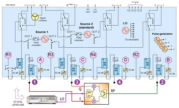
LO is used as the RF carrier signal.
RF is the modulated output.
The two PNA internal sources are used as the converter’s quadrature inputs.
Connect to ports 1 and 3 using the same frequency range but with a phase offset of 90°.
An external RF Source is connected to the LO input(s).
When using a Fixed LO, there is no need to control the source.
Connect the output to port 2.
On the PNA front panel, press Meas, then [Measurement Class]
Select Differential I/Q, then either:
OK delete the existing measurement, or
New Channel to create the measurement in a new channel.
A Differential I/Q measurement is displayed.
TIP: Set up one channel, then use Copy Channel to create additional channels (Trace/Chan, Channel, Copy Channel)
All five channels will have the following ranges:
Click Stimulus, then Frequency, then Differential IQ Setup
Click New three times for a total of 4 ranges.
Click Edit in each range, then enter the following:
F1: 10 MHz to 2.4 GHz; IFBW 1 kHz; Uncheck Couple
F2: 2.5 GHz to 2.5 GHz (CW); IFBW 1 kHz; Uncheck Couple
F3: IFBW 1 kHz; Check Couple; Couple to: F2; Offset: F1, Check UP
F4: 2.49 GHz to 100 MHz; IFBW 1 kHz; Uncheck Couple
TIP: Set up Ch 2, then use Copy Channel to overwrite channels 3 and 5.
Click Stimulus, then Frequency, then Differential IQ Setup
Click New three times for a total of 4 ranges.
Click Edit in each range, then enter the following:
F1: 1.2 GHz to 1.2 GHz (CW); IFBW 1 kHz; Uncheck Couple
F2: 2.5 GHz to 2.5 GHz (CW); IFBW 1 kHz; Uncheck Couple
F3: 3.7 GHz to 3.7 GHz (CW); IFBW 1 kHz; Uncheck Couple
F4: IFBW 1 kHz; Check Couple; Couple to: F2; Offset: F1, Uncheck UP
Click Stimulus, then Frequency, then Differential IQ Setup
Click New three times for a total of 4 ranges.
Click Edit in each range, then enter the following:
F1: 500 MHz to 500 MHz (CW); IFBW 1 kHz; Uncheck Couple
F2: 1.0 GHz to 4.4 GHz; IFBW 1 kHz; Uncheck Couple
F3: 1.5 GHz to 4.9 GHz; IFBW 1 kHz; Uncheck Couple
F4: 500 MHz to 3.9 GHz; IFBW 1 kHz; Uncheck Couple
Click Utility, then Configure, then External Device Configuration
Click New, then complete the dialog. Learn how.
Learn more about these settings.
Make the following Source settings:
Note: Do not attempt to control the phase of port 1. It will automatically get set to zero degrees when configured as the reference for port 3.
For ALL channels, on the Port 2 dialog:
Check Match Correction ON.
Then apply Match Correction for measurements of LO and sidebands (F2, F3, F4)
"Off+Match" is annotated on the Source setting dialog, although this is NOT shown in the images above.
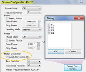
On any source in which a Phase setting is made, click Phase Control Setup. Decrease the Tolerance and increase the Max Iterations to improve phase accuracy. Learn more.
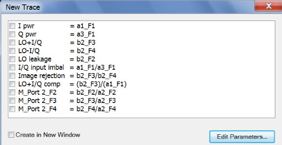
Note: Some of the parameters above are NOT displayed. These parameters can be used as diagnostic or troubleshooting parameters. For example, the “M_” terms are created when match correction is applied, but they are not usually displayed directly.
Click Trace/Chan, then Trace, then New Trace, then Edit Parameters.
Then do one of the following to create these Diff I/Q measurement parameters:
C:\Users\Public\Documents\Network Analyzer\Samples\Setups\DiffIQ\IQ_up_converter.xml
Once these parameters are defined, select (check) the parameters for each channel as follows:
For each channel, click Response, then Measure, then Select X-Axis
Make the following selections:
|
Channel |
X-Axis Domain |
X-Axis Source |
|
1 |
Frequency |
F1 |
|
2 |
Phase |
Port 3 |
|
3 |
Power |
Port 1 |
|
4 |
Frequency |
F2 |
|
5 |
Power |
Port 1 |
Click Response, then Start Cal, then Cal All Channels
Select the ports (in circle) for ALL channels.