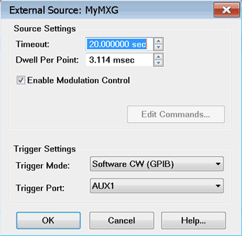
This dialog box is used to make external source settings.
Important Notes about External
Sources
First create an External Source (device)
by name (one-time). Learn
how.(Separate topic) Once you create and activate an external
source from the Configure
an External Device dialog, it becomes available
from the following VNA dialog boxes as well as the
softkeys and entry toolbar, as if it were an internal
VNA source.
Use the following dialogs to set the state, frequency,
and power level of the external RF source: By default, an external source is
de-activated
when the VNA is Preset or when a Instrument State
is recalled. This behavior can be changed with a Preference setting. External Keysight sources are usually
limited to 1601 points with List-sweep mode. To 'work
around' this limitation, divide the measurement among
multiple channels. For example, to attain a sweep
of 3200 points, create two channels of 1600 points.
You can also use manual source control which supports
Step-sweep mode. In this mode an external source can
have up to 65,535 points. See Synchronize
an External Source for help with manual source
control. External sources should always share
the same 10
MHz Reference signal as the VNA. Connect a BNC
cable from the VNA 10 MHz Ref Output to the External
Source Input. All newly-activated sources are preset,
with source power OFF. Source power must be turned
ON in the Power
dialog. Frequency Offset must be enabled
in the FOM
dialog. The same source can NOT be used more
than once in the same channel. The VNA automatically controls all
trigger settings for the external source. See
EXG Sources
configuration note. |
Source Settings
Timeout
(sec) Sets the VISA timeout and will stop processing
additional SCPI commands on the first error and will put the measurement
into hold.
Dwell per
point (ms) Applies a dwell in Hardware List triggering
ONLY. Set the time (in milliseconds) the external source will
wait before data acquisition.
Enable Modulation Control
- Enables modulation of an external modulation source to be controlled
from a source dialog.
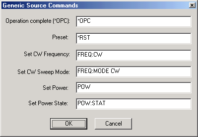
Edit Commands
Provides a method to send SCPI commands to AGGeneric
(not listed) sources.
Trigger
Settings and Physical Connection diagrams
Note: The
VNA controls ALL external source trigger settings automatically
(except for those on this dialog). All settings in the External
Trigger dialog are ignored.
Trigger Mode
Software
CW (GPIB) Slowest method.
The external
source receives each CW frequency from the VNA over GPIB,
USB, or LAN. No other trigger cables are required. Although
a Trigger Port selection may be available, it is NOT used.
Hardware List (BNC) Fastest
method (not available in M937xA).
NOT available
for AGGeneric (not listed) sources. The external
source receives a list of CW frequencies from the VNA, then
receives trigger signals though a rear-panel connector when
appropriate from the VNA. If the
number of data points used in the measurement exceeds the
capability of the external source, the VNA automatically switches
to Software CW (GPIB) trigger mode. This will slow the measurement
significantly.
Trigger
Port Used ONLY for
Hardware List Trigger Mode. Select the VNA rear
panel connector to be used for triggering. The
sources must be connected as follows:
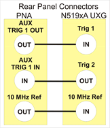
The
following diagram shows the connections between the PNA (AUX TRIG
1 or 2 can be used) and N519xA UXG signal generator.

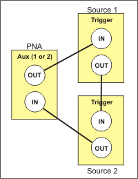
For
more than TWO sources, some will need to be connected using
the following daisy chain image. For example, with three external
sources, two could be daisy-chained to Aux 1 while the third
is connected by itself to Aux 2.

Notes
Source
1, which receives the trigger out of the PNA, must be the
first source listed on the External
Devices Configuration dialog box. Devices
are listed in the order in which they are created. You may
have to delete, then re-create a source to move it down on
the list. Connect EXG
sources as follows:
Note: The VNA AUX TRIG 2 can
be used instead of VNA AUX TRIG 1.
|


