The following is a step-by-step example illustrating how to measure a 1-stage mixer in swept LO mode using FCA Scalar Mixer Calibration.
There are fewer components required for SMC as compared to VMC, and fewer measurement steps. You can now make relative phase measurements with SMC. Also, ONLY SMC (not VMC) can measure the reverse conversion loss of the mixer.
This procedure can also be used for making fixed LO measurements, which is quite similar. Although a second source is still required, when using an external source, the physical triggering cables between the PNA and External Source are not required.
PNA-X or PNA 'C' models
with option 083 (FCA) or option 082 (SMC)
with PNA Rev. A.09.33 or above.
Note: This example has been updated to show keystrokes for the FCA User Interface available with PNA Rev. A.09.33 and above.
GPIB External Source. Not necessary when using PNA-X with Internal Second source.
ECal module with connectors that match the Input and Output connectors of the DUT. You can use adapters to make the ECal module match the DUT connectors, but first perform an ECal user-characterization with the adapters attached. ECal makes the FCA calibration much easier.
GPIB or USB power meter / sensor
Cables and adapters
Note: This procedure refers to an External Source to control the LO. If using a PNA-X with an Internal second source, an external source is not necessary. Connect the LO directly to the second source output.
The example device is a down-converter mixer with the following characteristics:
LO and Input Frequency Range: 2 GHz to 4.2 GHz
Output Frequency Range: DC to 1.3 GHz
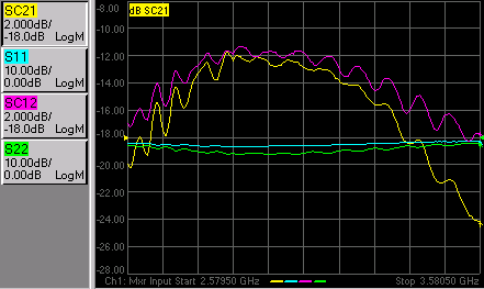
We will measure:
Fwd Conversion Loss (SC21)
Input Match (S11)
Output Match (S22)
Reverse Conversion Loss (SC12)
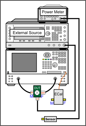
Connect the devices as shown in the following diagram:
The DUT can be connected to any PNA ports. Learn more.
This procedure uses DUT input to PNA port 1 and output to PNA port 2.
This procedure refers to an External Source to control the LO. If using a PNA-X with an Internal second source, an external source is not necessary. Connect the LO directly to the second source output (port 3 or port 4 on a PNA-X).
If using a GPIB power meter, connect the power meter to the external source GPIB connector. If using a USB power meter, connect it to any unused USB port.
If using a PNA-X with an Internal second source, the following three steps are not necessary. Connect the LO directly to the second source output.
Using a GPIB cable, connect the PNA GPIB controller port to the external source GPIB connector.
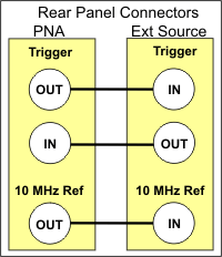
Using two BNC cables, connect the Source and PNA Trigger connectors as shown in the following image. This is not necessary when making fixed LO measurements.
Using a BNC cable, connect the PNA 10 MHz Reference Output to the Ext. Source 10 MHz Reference Input.
For this document:
Front-panel hardkeys are formatted as "Press Trace"
Front-panel softkeys are formatted as "Press [S11]
Menus are formatted as "Click System"
Connect the DUT.
On the PNA, press System, then [Configure], then [Power Meter Settings].
Under Interface, select GPIB, then enter the power meter address. Or select USB, then select the USB power meter that is connected to the PNA.
Press Preset to make sure you are starting with a known state.
Press Meas then [Measurement Class], then Scalar Mixer/Converter, then OK. At the Confirm... dialog, click OK. An S11 trace is created.
Press [SC21] to replace the S11 trace.
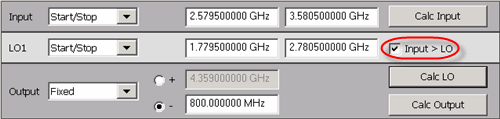
Press Freq then Input to start the Mixer Setup dialog.
On the Mixer Frequency tab, enter the Mixer setup values as shown in the image below.
Notes:
To provide quicker access to the Mixer Setup dialog, use the Setup softkey. Learn how.
Rather then enter ALL of the frequency settings, you can enter the Input and the Output frequencies, then click Calculate LO.
If Input>LO is NOT checked, the PNA assumes you want the Input < LO frequencies, and higher LO frequencies are calculated as a result.
The LO power level setting specifies the power out of the external source; not at the DUT) unless an LO power cal is performed.
When the settings are valid, the background color around the Apply button is available.
On the Mixer Setup tab:
Change LO1 to either an internal PNA source or a pre-configured external source.
To configure an external source:
Click Add Source in the upper-right corner of the Mixer Setup dialog.
Complete the External Source Configuration dialog.
If there is a problem communicating with the source, the PNA will display an error. See Problems?
Click OK to return to the Mixer Setup dialog.
The new external source is now available as an LO1 selection.
Save the mixer settings in a file so you can recall them easily. Click Save…, then type a descriptive filename, such as “FixedOutputMixer”.
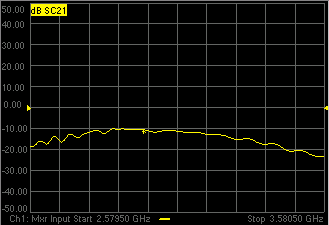
The trace should begin to sweep as the external source steps in frequency. It should look something like this:
Problems?Not sweeping:
Problems communicating with the source:
If the source is sweeping, and the PNA Input is sweeping, but there is still no output.
|
Tip: You can optionally calibrate the LO Power level at the DUT using a standard Source Power Calibration. Select the source port in the Source Power Cal dialog.
Disconnect the DUT.
Connect the ECal module to a PNA USB port.
Press Cal, then [Start Cal], then [Cal Wizard]. Because the SC21 measurement is active, the Cal Wizard automatically begins an SMC calibration.
At the Calibration Setup dialog, click Next.
At the Select DUT Connectors and Cal Kits dialog, for DUT Port 1 select the connector type and gender of your DUT INPUT. For DUT Port 2 select the connector type and gender of your DUT OUTPUT. Then select ECal as the Cal Kit to use for each connector. Click Next.
At the Scalar Mixer Calibration Step 1 of 2 dialog, connect the power sensor to the Port 1 test cable, then click Measure. The data will be used to correct for input mismatch errors.
At the Scalar Mixer Calibration Step 2 of 2 dialog, connect the ECal module Port A to the Port 1 cable, and Port B to the Port 2 cable. Then click Measure. This portion of the calibration gathers the linear (non-frequency-translating) error terms of the test setup at the input and output frequencies.
At the Calibration completed dialog, you can choose to save the SMC calibration as a User Cal Set. Otherwise, click Finish to complete the SMC calibration. Correction is turned ON and applied to the SMC trace.
When an external source is sweeping, the measurements are much slower. When correction is ON, you will see that there are times when nothing is happening on the screen. This is because there are background measurements being made but not displayed.
This is exactly the same as when full 2-port correction is applied to an S-parameter. All four parameters are measured, then correction is applied, then all four measurements are updated. This occurs much faster when there is no external source. With correction OFF, the traces are updated as the data is measured. You can see this taking place by creating the following measurements.
Press Meas then [S11], [SC12], and [S22] to add these measurements to the same channel.
While the source is sweeping, watch the source port indicator on the front of the PNA. First, the port 1 indicator will light for two sweeps, then the port 2 indicator will light for 2 sweeps. During the last sweep, all 4 traces update.
Press Cal, then [Correction OFF]. Notice that the relevant traces update as the sweep is occurring.
With the SC12 measurement you can see the reciprocity of the mixer.
Note: With the recent improvements to FCA, this step is MUCH easier than before. SMC forward and reverse measurements can now reside in the same channel and are calibrated automatically at the same time.