Configure the Port 2 'B' receiver port front-panel loops to a vertical orientation as shown here.
Block diagram showing port 2 thru coupler main arm to B receiver.
A Phase Reference calibration is performed to simplify the SMC+Phase calibration process.
In this topic:
Greatly simplified phase measurements on mixers.
A Reference Mixer or Calibration Mixer is NOT required.
Works well with segmented sweeps, and mixers with 2-stage LOs.
One of the following Keysight Comb Generators (Phase Reference):
U9391C (26.5 GHz)
U9391F (50 GHz)
U9391G (67 GHz) - Receiver attenuation must be used.
Note: The U9391-60009 sine-to-square wave is recommended when using the instrument’s 10 MHz reference output as the driving source to the comb generator. Connect between the instrument’s 10 MHz output and the input to the comb generator. See the U9391 Technical Overview for more information.
Power meter or USB power sensor.
S-parameter Cal Kit (mechanical or ECal module).
For measurements below 55 MHz, an additional 'Unknown mixer' is required. Learn more.
For measurements between 50 GHz and 67 GHz, an additional high-pass filter is required. Two back-to-back Keysight V281A waveguide-to-coax adapters is recommended.
Note: The 67 GHz comb generator creates a large pulse for generating useful harmonics up to 67 GHz. At low frequencies, receiver attenuation must be used to prevent overloading the PNA receiver due to the large signal. However, above 67 GHz, the extra receiver attenuation causes degradation in the signal-to-noise ratio (SNR) of the high harmonics, which would result in noisy phase calibrations. In order to prevent overloading and get good SNR, the receiver attenuation is removed and a high-pass filter is inserted between the comb generator and the PNA's test port. The calibration wizard provides extra steps to guide the user to insert the filter.
Available with opt. 083 (NOT with opt. 082).
Swept LO measurements are NOT allowed.
Lowest frequency for Phase Reference Cal is 10 MHz.
A Phase Reference Cal is performed, saved, and later recalled during a SMC Calibration. This is sometimes referred to as a 'tier 1" calibration. Due to stability of the PNA, the Phase Reference Cal can be performed infrequently. It is typically performed over the full frequency range of the PNA or Phase Reference so that it can be applied to all SMC calibrations that will be needed in the future.
The Phase Reference is a comb generator which produces signals at the multiple of its input frequency. By driving it with the PNA 10 MHz reference output, the Phase Reference produces signals at multiples of 10 MHz with a flat phase response.
During the tier 1 calibration, the PNA port 2 (B) receiver measures the phase at each 10 MHz comb frequency in order to generate correction values. These correction values are stored to a Phase Reference Cal Set which can be recalled and applied to correct subsequent SMC+Phase measurements.
Although only the B receiver is phase calibrated, an S-parameter calibration is performed at specified test ports and used to transfer the characterization to other PNA receivers.
A power calibration is also performed on port 1 as part of the Phase Reference cal. It does NOT have to be performed again during the SMC Cal.
By itself, the phase reference can only be used to calibrate down to 55 MHz. With one additional unknown mixer connection, the phase reference calibration can be extended to the full frequency range of the PNA-X. The unknown mixer is also used to improve the quality of the phase reference calibration below 300 MHz.
With the unknown mixer process, the phase of the unknown mixer is measured as a down converter with the output frequencies set between 10 MHz and 600 MHz. By using the data acquired using the phase reference, the system is able to make produce calibrated measurements of the mixer above 300 MHz. The phase response of the unknown mixer is assumed to be linear, so the expected phase response of the mixer is extrapolated down to 10 MHz. The variation in the measurements versus the expected phase response is attributed to, and used to correct, the phase response of the PNA receivers from 10 MHz to 300 MHz.
Unknown Mixer Properties
The mixer must be able to output a signal from DC to 1GHz.
Over these frequencies, the delay response of the mixer should be constant. Therefore, the unknown mixer must be passive, with no filtering or amplification.
Add a 10dB attenuator on the mixer input and output to minimize mismatch effects.
Connect the U9391 Phase Reference to a DC power supply. See the U9391 Technical Overview for more information.
The green wire is “ground”.
The red wire is + 15Vdc. The U9391C and U9391F only require +12 Vdc.
The black wire is not used.
Connect a cable from the PNA rear-panel 10 MHz Reference signal output to the U9391 input. The cable should be as short as possible.
Note: Note: The U9391-60009 sine-to-square wave is recommended when using the instrument’s 10 MHz reference output as the driving source to the comb generator. Connect between the instrument’s 10 MHz output and the input to the comb generator. See the U9391 Technical Overview for more information.
Connect the U9391 output directly to the PNA test port 2.
Insert the U9391 USB connector into any of the PNA USB ports.
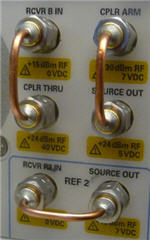
Because of its low-frequency roll off, the coupler on Port 2 must be reversed which bypasses the coupled arm. Flip the port 2 front loops as shown in the following image. This increases power to the receiver by approximately 16 dB at low frequencies and removes noise from the measurement.
Configure the Port 2 'B' receiver port front-panel loops to a vertical orientation as shown here. |
Block diagram showing port 2 thru coupler main arm to B receiver. |
The Phase Reference Cal Wizard steps will show the appropriate prompts.
When Unknown Mixer is enabled (Start Frequency is 10 MHz)
Reverse the Port 2 loops.
The input and output match of the unknown mixer is measured. Then SC21 using 100 averages.
Phase Reference measurement and S-Parameter calibration below 50 GHz.
S-parameter cal is NOT performed when Omit Coupler Measurements is checked.
Reverse the Port 2 loops.
When using the 67 GHz phase reference, use receiver attenuator or external attenuator.
When mixer output is above 50 GHz, Phase Reference measurement and S-Parameter calibration.
Connect 50 GHz high pass filter to phase reference output.
Reverse the Port 2 loops.
Receiver attenuator or external attenuator is NOT used.
Full band power sensor measurement.
Connect Power Sensor to Port 1.
Port 2 coupler in normal position.
Full band S-parameter calibration.
Connect standards to Port 1.
Port 2 coupler in normal position.
High-pass filter is NOT used.
Receiver attenuator or external attenuator is NOT used.
Use Unknown MixerCheck to use an Unknown Mixer to calibrate the PNA receivers below 55 MHz. The Start Frequency becomes 10 MHz and can not be changed. Learn how it works. Ports
Omit Coupler MeasurementsThis choice can be selected when the stop frequency is less than or equal to 50 GHz. Enabling the checkbox simplifies the calibration procedure by reducing the number of calibration steps required, with some tradeoffs. Clearing the checkbox will always result in the most accurate phase-reference calibration. With the checkbox selected:
Start / Stop FrequencySelect the start and stop frequency of the Phase Reference Cal. Subsequent SMC+Phase calibrations MUST be the same or a subset of these frequencies. Interpolation is performed when the 10 MHz 'grid' of characterized frequencies is off from measurement frequencies.
Source AttenuationSelect the attenuation value for the PNA source port.
Phase ReferenceWhen the Phase Reference is detected by the PNA, it should appear in this field. If it does NOT appear here, try a different USB port, then click Refresh. Phase Reference Connector type and gender. When the Phase Reference does NOT mate directly with the test port, you can add a well-behaved, broadband (no filters, waveguide, etc.) adapter to the Phase Reference and ignore it. That is because the adapter will stay with the Phase Reference and the calibration plane will still be the PNA test port connectors. The adapter adds constant delay; the deviation in delay is what is being calibrated out. Loss in the adapter is not a concern because the adapter is not used during the S-parameter and the power meter portion of the cal. Cal Kit Connector Select the connector type and gender of your Cal Kit. Only ONE connector type and gender is specified. This is because the entire Phase Reference cal is performed at the PNA test ports to reduce the effects of cable flex in the characterization. There may be times when an adapter or connector-savers are used to connect the phase reference and cal standards to the test ports. In these cases, for highest accuracy use that adapter style and gender for ALL connections to ALL test ports. The effects of the adapter will be de-embedded automatically during subsequent SMC+Phase calibrations. Note: For highest accuracy, perform the phase reference cal at the test ports. Cal Kit Select the Cal Kit that will be used to perform the S-parameter Cal. B Receiver AttenuationThe 67 GHz (U9391G) phase reference outputs too much power and overloads the PNA Port 2 (B) receiver. Use at least 16 dB and not more that 20 dB of receiver attenuation to make accurate measurements using that phase reference. This message is shown when a 67 GHz phase reference is connected to USB. The B receiver attenuator control is shown if your PNA has receiver attenuators. Otherwise, connect external attenuation to the U9391G output when prompted. |
Unknown Mixer Settings (Phase Reference Cal Wizard) dialog box help |
The following wizard pages appear when Unknown Mixer is checked on the previous page:
Select LO source The LO can be an internal 2nd source or an external source. Sources Click to start the External Devices dialog where you can select or configure an external RF source. LO Frequency Select a frequency that results in the unknown mixer output of 10 MHz to 600 MHz using this formula: Input = LO + Output. Note: For best results, use the default LO frequency which avoids the PNA-X input (source) frequency band crossings.
The Port 2 coupler must be reversed for these measurements. Learn how.
|
Power Cal Settings (Phase Reference Cal Wizard) dialog box help |
A power calibration is performed on port 1. This is done to simplify subsequent SMC calibrations since the power calibration will not need to be repeated. For highest accuracy, connect the power sensor directly to the test port with no adapter. Learn more about these settings.
|
5. When finished, press Next> Power sensor A
Connect the power sensor to port 1 test port. SOLT cals are performed at the test ports.
Phase Ref Cal Finished
Enter a name for the Phase Ref Cal, then click Finished. During subsequent SMC calibrations, select the Phase Reference Cal Set at the SMC Cal setup dialog. Learn more. Specify Delay
If you know the delay value of the Unknown Thru connection, enter it here. Otherwise, click OK to accept the calculated value.
|