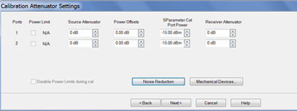
This dialog shows the Power, Attenuator, and IFBW settings for
the Cal All calibration. The default values for the Cal All session
are the preset values of a standard S-parameter channel. These
values are not necessarily the same as those of the channels that
are selected for calibration. When there are differences in measurement
path (switch) settings between the Cal All channel and the selected
channels, these differences are detected by Cal All and additional
measurements are made for each path condition. These additional
measurements allow Cal All to produce error terms appropriate
for each of the selected channels. In general, the Cal All session
should be performed at a power level that is high enough to prevent
noise in the error terms. However, an increase in power could
cause compression or damage to the analyzer receivers. The following
settings allow you to increase the power level ONLY during the
Cal All session.
Power Limit (Disable)
Cal All shows you when power limits are
enabled. This setting provides you a convenient way to TEMPORARILY
disable these limits in order to take advantage of the power settings
available in Cal All. If power limits are on, your DUT is
probably a high-gain device and the attenuator settings in your
channels are high resulting in lower power at the cal reference
plane. This lower signal can result in noisier measurements
during the acquisition of cal. This situation is precisely what
Cal All is intended to improve. Cal All allows you to configure
the calibration conditions for better signal-to-noise performance
during the cal while leaving your DUT conditions alone. You can
elect to clear the “Disable Power Limits during cal” checkbox
when you prefer to calibrate at a higher power level than is allowed
by your limit. The limit is restored after the Cal All session.
Source / Receiver Attenuator
By default, the Cal All calibration is performed
with Source and Receiver attenuators set to 0. Change the Source
or Receiver attenuator settings when external hardware (such as
a booster amplifier) would cause the analyzer receivers to be
compressed or damaged.
You may also want to change the attenuator
or path configuration settings to force the cal channel to match
settings of the selected channels. If all of the selected channels
are set to identical hardware settings, it may be better to apply
these settings to the cal channel. For example, if your channels
all use a 5 or 10 dB attenuator step at port 1, you might elect
to change the Cal All channel to use the same low attenuator settings.
This will result in the cal measurements being made under
the same path conditions as the channel and it will eliminate
the need to mathematically compensate for the difference. However,
if large attenuator values are used, the default Cal All settings
will likely improve your results.
S-Parameter Cal Port Power
Set the power level at which the S-Parameter
cal is performed.
Power Offsets
Power Offsets are channel-scoped. Consequently,
offsets that you already set are NOT automatically copied to the
Cal All session. This setting allows you to also apply a
Power Offset during the Cal All session. Learn
about Power Offsets.
Noise
Reduction
This button accesses the following dialog
for settings that help reduce trace noise and the noise floor
which can lead to better dynamic range and more accurate measurements.
Learn more.
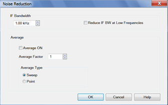
IF
Bandwidth
Set the IFBW
used to perform the Cal All calibration. The default IFBW setting
of 1 kHz is a good nominal setting for most measurements. Lowering
the IFBW removes noise from the calibration measurement, but also
causes slower sweeps.
Always
ON
Check to enable
averaging.
Average
Factor
Specifies the
number of measurements that are averaged. Range of 1 to 65536
(2^16).
Average
Type
Sweep
Each data point is based on the average of the same
data point measured over consecutive sweeps. Learn
more.
(Sweep)
Restart Begins a new set of measurements that
are used for the average. Applies only to Sweep averaging - NOT
Point.
Point
Each data point is measured the number of times specified
by the Average Factor, and then averaged, before going to the
next data point. Learn
more.
Reduce
IF BW at Low Frequencies
When
this box is checked, the PNA uses a smaller IF Bandwidth than
the selected value. Learn
more.
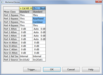
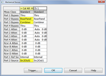
Mechanical
Devices
This button
accesses a dialog that shows the settings for all active channels.
These settings are shown side-by-side for easy comparison. Learn more. |