SMC+Phase
With SMC you can optionally measure phase. This feature is available with the S9x083A/B. SMC + phase is NOT offered in the N523xB.
In this topic:
See Also
SMC Measurements and Calibration
Overview
There are three methods used in the VNA to calibrate SMC+Phase measurements. All three methods rely on newer phase-coherent synthesizers in the VNA to produce phase capability in frequency offset measurements.
With the first two methods, during an SMC calibration, the phase delay through a Calibration Mixer is measured and compared to the known delay. The difference is used to correct subsequent SMC+Phase measurements.
A Calibration Mixer is required with the first two methods.
-
Enter the known delay into a dialog.
-
Uses the known delay at various frequencies from an *s2p file from a mixer characterization. You create the *S2P file from a separate Mixer Characterization. This method is NOT supported with Cal All.
-
Uses a Phase Reference to perform a 'tier 1' calibration. A Calibration Mixer is NOT required with this process. Learn more about this process.
Notes
-
A Reference Mixer is NOT required with any of these methods as it is with VMC.
-
SMC+Phase can be measured on Converters with an Embedded LO. Learn how.
-
Phase can be measured with Power Sweeps.
-
Phase can NOT be measured on Swept LO measurements.
-
It is especially important with SMC + Phase measurements to connect the 10 MHz reference signal of an external source to the VNA.
-
you can use a Phase Reference Cal Set with Independent power cals for input and output ports (no thru). Learn more.
How to make SMC+Phase measurements
-
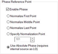
On the Mixer Sweep tab, check Enable Phase, then select the Phase Reference Point.
|
SMC Mixer Sweep tab - Phase Settings help |
|
Enable Phase Check to perform phase measurements. You can also enable phase measurements at the SMC Cal Setup dialog. Phase Reference PointThe SMC Phase measurement technique provides for a coherent phase relationship from one frequency to the next in each sweep. However, for instruments with fractional-N-based sources, the phase measurement of the first data point is random from sweep to sweep. This initial phase offset does not impact measurements such as group delay or deviation from linear phase. In order to keep a phase trace from appearing random sweep-to-sweep, all phase data in the sweep is normalized against a single point. This results in a stable, normalized phase trace. For this normalization, select the measurement point that has the best signal-to-noise ratio. The phase at the selected point will always be zero before calibration and any electrical delay is applied. When phase normalization is used in conjunction with Segment Sweep, only the choice Normalize Middle Point is available. For instruments with direct-digital-synthesis (DDS)-based sources, an additional choice is available called Use Absolute Phase. With this choice, the phase of the internal sources and internal LO start up with a repeatable phase at every point, giving stable and repeatable phase sweep-to-sweep. Phase normalization is not used in this case. This feature allows SMC+Phase to make measurements that previously required the Vector Mixer/Converter (VMC) measurement class and the associated reference and calibration mixers. One example is measuring phase changes that occur within a device, for example, due to an internal phase shifter in a transmit/receive module. Another example is measuring the absolute phase variation among various frequency converters or mixers due to internal path-length differences. Limitation when Use Absolute Phase is selected:
Note: Absolute Phase is a Licensed Feature. Learn more about Licensed Features. |
-
Select a Phase Format for the SMC measurement: click Response, then Format, then phase, unwrapped phase, or group delay.
-
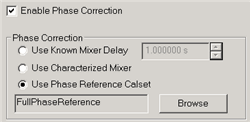
During SMC Cal, at the Cal Setup dialog, select the Phase Correction method as follows:
|
Enable Phase Correction Check to enable Phase measurements. This can also be done during the mixer setup. Phase CorrectionChoose one of the following methods to specify the known delay through the characterized mixer. With the first two methods, the phase delay through a Calibration Mixer is measured and compared to the known delay, either entered, or stored in an *.S2PX file.
|
Measuring phase on Mixers below 55 MHz
Measuring phase on mixers below 55 MHz is challenging for the following two reasons:
-
The PNA-X couplers have significant losses at these low frequencies. The PNA-X automatically reduces the IFBW at low frequencies in order to compensate for the coupler roll-off. And with SMC+Phase, we recommend setting 100 averages in order to reduce the noise of the SC21 delay measurement. These two settings combine to make the measurement speed VERY slow.
-
Recommendation: When measuring a downconverter with an output frequency below 55 MHz, check the “Reversed Port 2 Coupler” checkbox on the SMC Mixer Sweep tab and reverse the Port 2 coupler for the DUT measurement. With this setup, the IFBW is no longer reduced when measuring the output power. This significantly speeds up the measurement without reducing accuracy.
-
-
The PNA-X has a significant number of frequency bands below 55 MHz. SMC+Phase must have multiple measurement points within every frequency band.
-
Recommendation: Select the number of data points to yield a point spacing of NO MORE than 200 kHz per point. Segment Sweep can be used so that the point spacing above 55 MHz is not as dense.
-
Comparing SMC+Phase with VMC Phase Measurements
SMC phase measurements do NOT require a reference mixer, and are therefore easier to make than VMC phase measurements. Also the SMC calibration mixer is only required to have a known delay value, although an S2P characterization file provides more accurate results. The Phase Reference method provides the highest accuracy phase measurements for mixer/converters.
-
When measuring converters with an embedded LO, SMC with phase can provide results that are as stable and free from sweep-to-sweep jitter as VMC.
-
When measuring converters with an external LO that is shared with the reference mixer (as shown in the VMC Setup diagram), VMC provides results that are more stable than SMC+Phase.
How to improve the stability of SMC+Phase measurements
Stable phase measurements are attained by increasing Sweep Averaging, and sometimes lowering the IFBW, until you attain the desired compromise between sweep time and trace jitter (the amount of random phase change at a single data point). For SMC+Phase, the default IFBW is 10 Hz, and 1 average. During calibration, the Averaging factor is temporarily multiplied by 4 to ensure an accurate phase calibration.
The following procedure shows how to view and improve phase jitter:
-
Create an SMC+Phase channel (Click Response, Measurement Class).
-
Enable Phase with SMC (See above) On the phase trace (to follow) notice that the only point that has NO jitter is the data point that you selected as the Phase Reference point.
-
Change the measurement to IPWR: (Click Response, Measure, IPWR)
-
Change Format to Phase. (Click Response, Format, Phase)
-
Normalize the trace. (Click Math, Memory, Normalize) Learn more about Normalization.
-
Autoscale the trace. (Click Response, Scale, Autoscale).
-
Optionally monitor the jitter with Trace Statistics (Std Dev)
-
Increase Averaging and possibly lower IFBW to improve jitter. (Click Response, Avg BW, then Averaging). Use a MINIMUM of 10 sweep averages (never use Point Averaging).
-
After the adjustments are made, change the measurement back to your measurement of interest.
-
When measuring a new DUT, restart Averaging.
How to Calibrate a 2-stage (LO) SMC+Phase Measurement
Note: The following discussion does NOT pertain when a Phase Reference cal is used to correct the SMC+Phase Measurement.
When calibrating a dual-stage SMC+Phase measurement for group delay using a characterized mixer, the channel setup requires frequency values for two LOs, but the characterized-thru mixer uses only one LO. The frequencies of LO1 and LO2 are different. There are two ways to overcome this challenge:
-
Before the calibration, set the LO that is provided by an external source to uncontrolled. Then manually set the frequency of this external source to the LO frequency that gives the same input and output frequencies, and the same sweep direction, as the dual-stage setup. Perform the calibration under this condition. After the calibration, return the LO to controlled so that its frequency will be properly set during the measurement of the DUT.
-
Configure a 1-stage mixer setup, with the LO set to the frequency that gives the same input and output frequencies and the same sweep direction as the dual-stage setup. Perform the calibration under this condition. Save the calibration data as a user calset. Configure the dual-stage case, and apply the 1-stage calibration.

