The procedure in this topic describes how to perform a calibration using the Cal All Calibration Wizard method, which allows multiple channel calibration in a single session.
Note: Beginning with the A.12.80 release, Cal All has been extended in order to deal with the new Low Frequency Extension option. If a user has a mixture of LFE and non-LFE channels and they would like to use Calibrate All to calibrate them at the same time, two calibration channels are created to account for the hardware differences between the two situations. When using the GUI or COM to set calibration and stimulus conditions, the settings are applied to both calibration channels. With SCPI, the user can query the primary guided calibration channel using SYST:CAL:ALL:GUID:CHAN:VAL?. This will return the primary calibration channel. When subsequent Guided Cal commands are used, settings will be transferred to the second calibration channel. If there is a desire to set these settings separately, the user should query for all Cal All Calibration channels with SYST:CAL:ALL:GUID:CHAN:LIST?. The user should set values for the primary calibration first, and then secondary calibrations. When initializing the calibration and acquiring steps, use the primary cal all channel number.
For information about other calibration methods that can be used, refer to the following links:
Ensure that the measurement classes to calibrate are active.
Press Sweep > Source Control > LF Extension ON.
Ensure that the measurement frequency range is set properly.
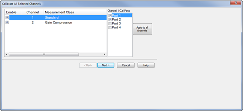
Press Cal > Main > Other Cals > Cal All... to launch the following dialog showing the active measurement classes:

Check the measurement classes to calibrate.
Select the ports, then click on the Apply to all channels button to apply the port selections to all channels.
Click Next, then confirm or change the calibration properties in the Measurement Class Cal Properties dialog.
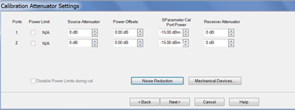
Click Next. to access the Calibration Attenuator Settings dialog.

In the Calibration Attenuator Settings dialog, perform the following:
Set the attenuator settings. Learn more.
Click on the Noise Reduction button to improve measurement accuracy. Learn more.
Click on the Mechanical Devices button to view all switches and attenuators in the VNA. Learn more.
Click Next, then select the DUT connectors and calibration kits in the Select DUT Connectors and Cal Kits dialog.
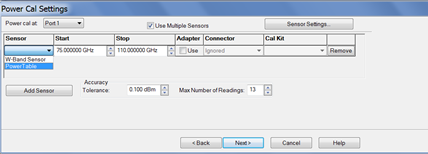
.Click Next to access the Power Cal Settings dialog.

In the Power Cal Settings dialog, perform the following:
Check Use Multiple Sensors if more than one power sensor is needed to cover the frequency range then select a sensor from the Sensor down menu.
Learn more about Accuracy Tolerance and Max Number of Readings.
Click Next and follow the calibration process until completed.