Physical Mode: Basic Downlink Setup
This example shows how to configure and download a basic downlink waveform
to the signal generator using Physical as the frame setup mode.
Step
1: Select a Quick Setup
Step
2: Configure the Project Property Parameters
Step
3: Configure the Signal Generator Settings
Step
4: Configure the Downlink Frame Structure
Step 5: Generate and Download the Waveform
Step 1: Select a Quick
Setup
Click Quick
Setup in the tree view. Click the 802.16-2004
(WiMAX) button in the right pane to access the main window.
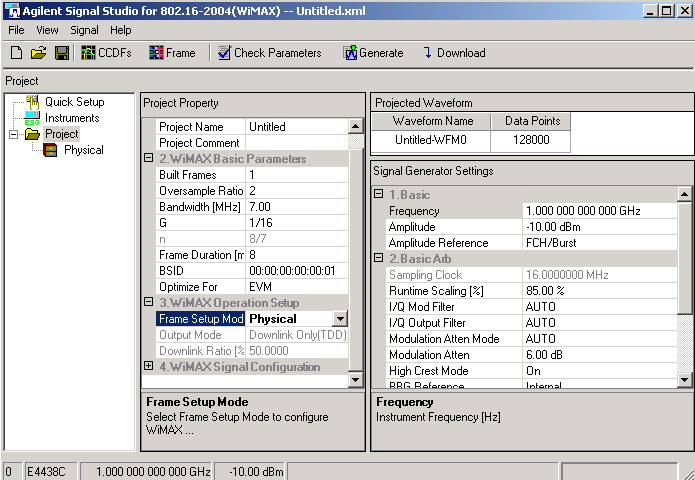
Notice that Project is highlighted
and the parameter view displays three panes: Project Property, Projected
Waveform, and Signal Generator Settings.
Step 2: Configure the
Project Property Parameters
In
the Project Setup table:
Change the default Project
Name (Untitled) to a unique name of eight characters or less. You
may also enter a Project Comment
to describe the waveform.
Use the WiMAX Basic Parameters
table to edit waveform generation parameters. Set up a waveform with the
following characteristics:
Select Physical
for the frame setup mode in the WiMAX Operation Set Up pane.
In the WiMAX Signal Configuration
table:
Leave the default settings
for MARKER1-4:
Frame Start, None, Burst Envelope, and ALC Hold,
respectively.
|

|
These
markers are linked to the marker settings in the Basic Arb section of
Signal Generator Settings. Markers3-4 are used by the software to control
the RF blanking and ALC settings
for waveform playback, so they should not
be modified. |
Observe the waveform's length
characteristics in the Projected Waveform pane. The Data
Points cell is calculated as follows: [Data Points] = [Sampling
Clock] * [Frame Duration] * [Built Frames].
Step 3: Configure the
Signal Generator Settings
Configure the signal generator's
frequency, amplitude, and arbitrary waveform playback parameters in the
Signal Generator Settings pane. Set Frequency
to 3.5 GHz and Amplitude to –10
dBm.
The signal generator's amplitude setting
refers to the average power level of the FCH/Bursts, as indicated by Amplitude
Reference. The preamble power level is defined in the standard to be 3
dB higher than the level of the rest of the burst, so it will always be
3 dB higher than the amplitude setting of the signal generator. If you
create a waveform that only has a preamble, select Preamble as the Amplitude
Reference.
|

|
The Amplitude
Reference also determines the portion of the waveform that is used by
the signal generator for ALC leveling. In some cases,
choosing the Amplitude Reference to be the preamble instead of FCH/Burst
may result in better RCE (EVM) since, in some cases,
the RCE (EVM) of the signal can vary based on the data
in the waveform. |
The sampling clock frequency
for the signal generator is automatically calculated as [Sampling Clock]
= floor(n * Bandwidth / 8000) * 8000 *OSR.
This is the same as the “sampling frequency” defined in the IEEE 802.16-2004
standard.
Step 4: Configure the
Downlink Frame Structure
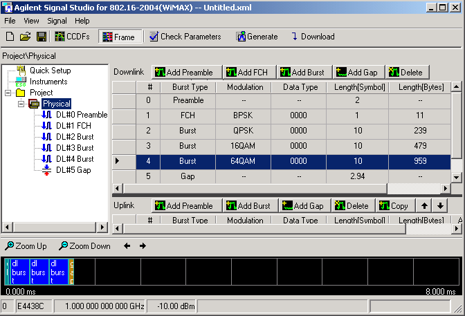
Click
Physical in the tree view. This displays the frame structure in
the right pane, with the downlink subframe on the top half and the uplink
subframe on the bottom half.
Click the Add
Preamble button.
Click the buttons, Add
FCH, Add Burst (three times),
and Add Gap in the right pane
to add an FCH, three bursts and a gap with their respective default values.
Notice that the new FCH and burst frame components are added to the table
and the tree view. The gap (also referred to as the transmit/receive transition
gap or TTG) allows the base station time to change from transmit to receive
mode.
Click Frame in the tool
bar to display a plot of the frame layout with the new FCH and bursts.
Clicking Frame again will hide the plot.
Edit
the burst parameters. Double-click in the first column in the table for
the item, or click on the item in the tree view on the left. A window
appears that shows parameters specific to the selected burst type. Change
the parameters as follows:
For DL Burst#2, change the
OFDM Symbol Length to 10.
For
DL Burst#3, change the Modulation
Type to 16QAM and the OFDM Symbol
Length to 10.
For DL Burst#4, change the
Modulation Type to 64QAM and the
OFDM Symbol Length to 10.
Click Physical
in the tree view to return to a view of the overall
frame.
Click the Check
Parameters button in the tool bar to verify that the configured
bursts do not exceed the length of the defined frame. If the configuration
is valid, a result message "Parameters are fine" will be shown
in the status bar at the bottom of the window. If not, a message "Defined
frame exceeds the maximum frame length" appears.
Step 5: Generate and Download
the Waveform
From the tool bar, click Generate. The software generates an
I/Q waveform file in accordance with the current physical channel configuration
and waveform generation setup. Waveform generation time varies proportionally
with the complexity and length of the waveform. Messages showing the waveform
generation progress and status are displayed in the status bar.
From the tool bar, click CCDFs to toggle the graph view on and
off. The graph view enables you to examine waveform characteristics, such
as baseband spectrum, I and Q signals, and CCDF curves, prior to downloading
the file to the signal generator.
From the tool bar, click Download to generate and download the
waveform to the signal generator. The waveform file automatically begins
to play. You can re-enable local control of the signal generator by pressing
the Local hardkey, enabling you
to modify signal generator settings from the front panel. The waveform
file cannot be modified after downloading it to the signal generator.
However, the carrier frequency and amplitude can be changed.
You can use the 89601A software (version 5.3) with Option B7S (802.16
Modulation Analysis) to view the waveform on a signal analyzer such as
the E4406A (VSA) or others in the PSA family.
Related Topics
Using
the MAC Editor
Frame
Plot View
Graph
View
DLFP Editor
Related Websites
IEEE
802-16-2004 standard
ESG product information
PSG product information
MXG product information
Agilent Signal Studio software


