MAC-Uplink
To configure uplink frame components using
MAC PDU frame setup mode:
Click Project  in the tree view. Ensure that MAC PDU is selected as the Frame Setup Mode
in WiMAX Operation Setup.
Click MAC-Uplink in
the tree view. The MAC-Uplink Settings window displays the common uplink
parameter settings in the top half and buttons for adding bursts (maximum
16) in the bottom half.
When you use the MAC PDU mode to configure WiMAX signals, the software
automatically generates the WiMAX waveform based on your configured MAC
description. Click Frame in the tool bar to view a
block diagram at the bottom of the window showing how the frame components
fit on a time axis.
MAC-Uplink Settings
1. Uplink Burst Common Parameters
UCD Count
Use this cell to enter the configuration change count of the UCD. This
is encoded in the UL MAP and UCD contents. It is incremented by one (modulo
256) whenever there is an uplink configuration change. Accepted values
are 0 (default) to 255.
UL Channel ID
Use this cell to enter the uplink channel for the message in the UCD.
Accepted values are 0 (default) to 255.
Ranging Back-off Start
Use this cell to set the initial backoff
window size for initial ranging contention, expressed as a power of 2.
This is encoded in the UCD message in the MAC layer. Accepted values are
0 to 15. The default value is 1.
Ranging Back-off End
Use this cell to set the final backoff
window size for initial ranging contention, expressed as a power of 2.
This is encoded in the UCD message in the MAC layer. Accepted values are
0 to 15. The default value is 7.
Request Back-off Start
Use this cell to set the initial backoff
window size for contention bandwidth requests, expressed as a power of
2. This is encoded in the UCD message in the MAC layer. Accepted values
are 0 to 15. The default value is 1.
Request Back-off End
Use this cell to set the final backoff
window size for contention bandwidth requests, expressed as a power of
2. This is encoded in the UCD message in the MAC layer. Accepted values
are 0 to 15. The default value is 7.
Uplink Start Time [samples]
This cell displays the timing offset from the start of the frame in
terms of an integer number of samples of the sampling frequency. The uplink
start time is determined based on the value of the downlink ratio set in the parameter view for TDD
signals. The value is zero for FDD.
Uplink Start Time [us]
This cell displays the timing offset from the start of the UL frame
in microseconds rounded to an integer number of samples. The uplink start
time is determined based on the value of the downlink ratio set in the parameter view for TDD
signals. The value is zero for FDD.
2. RTG Setting
Gap Interval [samples]
This cell displays the size of the RTG
as an integer number of samples of the sampling frequency.(If the frame
duration mode is continuous, you can edit this cell.) The maximum gap
size depends on the sampling rate, oversample ratio, cyclic prefix, and
frame size. Editing the Gap Interval [us] recalculates this value rounded
to an integer number of samples. The minimum and default value is zero.
Gap Interval [us]
This cell displays the size of the RTG
in microseconds.(If the frame duration mode is continuous, you can edit
this cell.) The maximum gap size depends on the sampling rate, oversample
ratio, cyclic prefix, and frame size. Editing the Gap Interval [samples]
recalculates this value. The minimum and default value is zero.
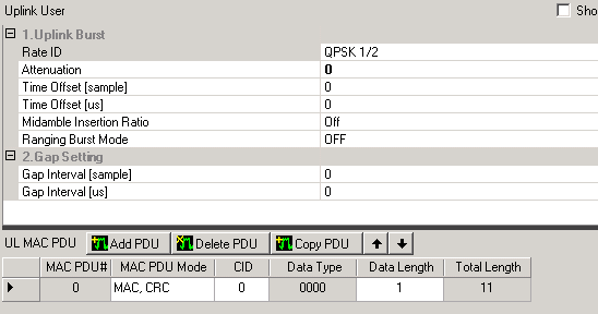
Uplink User
|

|
adds a user burst with a default MAC PDU. For each burst (maximum 16),
a data grid displays parameters that you can edit by clicking each cell.
You can also edit a full set of parameters and add up to eight MAC PDUs
per burst in the UL User window.
See Editing Tip.
|
|

|
deletes a previously added burst. |
|

|
adds a burst that has the same configuration as the currently selected
burst. |
|
 
|
swaps the currently selected burst with the one above it or just below
it in the table for that link. |
Related Topics
About
WiMAX
MAC PDU Mode: Basic DL/UL
Setup
Frame
Plot View
 in the tree view. Ensure that MAC PDU is selected as the Frame Setup Mode
in WiMAX Operation Setup.


