Open topic with navigation
AM Step
Step size in time and the amplitude of the carrier during the duration
of the pulse are user-defined. Note that AM step is an intra-pulse modulation
and not amplitude modulation from pulse to pulse. The amplitude offset
is a relative parameter and must be within the power limits of the signal
generator's baseband generator. The maximum amplitude is used as the reference;
all lower power levels are relative to the maximum amplitude step.
For the trapezoidal and raised-cosine built-in pulse types the step size
should sum to equal the pulse Width (100%-100%). For custom profile and
custom I/Q pulse types the step size should sum to equal the time duration
from the first point of data through to the last point of data. Selecting
the AM Step Modulation Type displays an AM step table shown in the figure
below. If the step size does not equal the pulse width, the AM steps will
be padded (if not enough steps), or truncated (if too many steps). Refer
to the padded
and truncated diagram for more information.
When using the AM Step modulation format
the ALC should be turned
off, or the ALC
Hold feature should be used. This prevents the ALC from trying to
level the AM step within the pulse.
To create the AM step table:
-
Select AM Step from the Modulation Type drop-down list
box.
-
Place the mouse pointer in the AM step table and click
the right mouse button.
-
Click  New Items
in the menu.
New Items
in the menu.
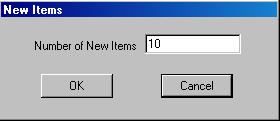
-
Enter the number of
index items
desired using the dialog box.
-
Enter the step size and amplitude for each index item.
In the following diagram the frequency offset and time duration relationship
for the table entries in the above figure are shown. Note that modulation
is applied only during the pulse Width (100%-100%) time interval and not
during rise and fall times. In the diagram below the last half of the
–15 dB step, and the
entire 0 dB step will not modulate the pulse because they occur after
the pulse width of 8 us. See the section on padding and truncating.