The Pulse Type menu provides access to the following pulse types:
The Pulse Details section of the form will change depending on the Pulse Type selected. If the Pulse Type is trapezoidal or raised-cosine, the pulse details section is the same as shown in the above Pulse Library form. Custom Profile and Custom I/Q pulse types use different pulse detail parameters.
This pulse type is defined by rise time, fall time, width, width jitter type, jitter deviation and modulation type. These parameters are described in the Pulse Parameters section. A trapezoidal pulse has a linear rise and fall time with a characteristic shape shown in the following figure:
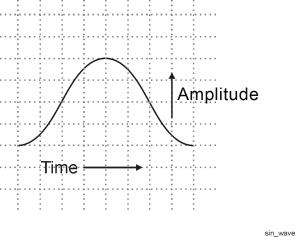
This pulse type is defined by the same parameters that describe a trapezoidal pulse. A raised-cosine pulse has sinusoidal rise and fall times with a characteristic shape as shown in the following figure:
This pulse type is described by user-defined pulse profile data. The pulse is defined by an index number and amplitude value. A pulse can be described using any number of points (index number) representing an amplitude level. The largest amplitude number in the custom profile data table is used to reference all the other amplitude data points. The Pulse Building application normalizes the profile amplitude data so that the maximum amplitude is 1.
The N7620B software will automatically resample the Custom Profile data if its sampling rate is different from the current Arb Sampling Rate. (The current Arb sampling rate is found under the button on the Pattern Library display.)
There are two ways to enter custom profile data: manually, or by using the Import function.
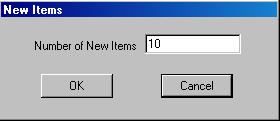
- Add new items by placing the mouse cursor in the Profile Data section of the form, click the right mouse button, and then select the New Items menu selection.
The ![]() New Items
dialog box allows you to enter the number of items (data points) used
to define the custom pulse. Once the number of items is entered you can
set amplitude levels that define each sample point. New items are added
to any items already present. If there are 20 items in the table and you
enter 10 in the New Items dialog box, the table will have 30 items. To
delete items, select the item or items (use the shift key and mouse pointer
to highlight the items you want to delete) then click the right mouse
button and select Delete.
New Items
dialog box allows you to enter the number of items (data points) used
to define the custom pulse. Once the number of items is entered you can
set amplitude levels that define each sample point. New items are added
to any items already present. If there are 20 items in the table and you
enter 10 in the New Items dialog box, the table will have 30 items. To
delete items, select the item or items (use the shift key and mouse pointer
to highlight the items you want to delete) then click the right mouse
button and select Delete.
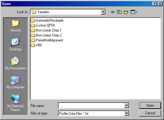
- This command button opens a ![]() dialog
that allows you to import a .txt file containing custom profile values
into the Profile Data table. The text file must be in a tab delimited
format. If you are using Microsoft
Excel to create custom pulse profiles use the Save as type: Text (Tab
Delimited) selection in Excel. The Pulse Building application can then
import that .txt file pulse definition. The waveform sample rate for the
imported custom profile data must match the sample rate in the Advanced
section of the Pattern Details form.
dialog
that allows you to import a .txt file containing custom profile values
into the Profile Data table. The text file must be in a tab delimited
format. If you are using Microsoft
Excel to create custom pulse profiles use the Save as type: Text (Tab
Delimited) selection in Excel. The Pulse Building application can then
import that .txt file pulse definition. The waveform sample rate for the
imported custom profile data must match the sample rate in the Advanced
section of the Pattern Details form.
There are 10 amplitude levels defined in the above figure. This example defines a CW pulse; no modulation present. Custom profile data can contain modulation. You can also add modulation by selecting a modulation from the Modulation Type drop-down list box. If a step modulation such as FM Step is used, the time duration for the total number of steps must equal the on time for the pulse. Refer to the section on modulation types for more information.
The pulse width, measured from the first data point to the last data point, should equal the (maximum index number)/sample rate. In the above figure the maximum index number is 10 and the sample rate is 10 MHz; therefore, the pulse width should equal 1000 ns. The waveform sample rate for the imported custom data must match the sample rate in the Advanced section of the Pattern Details form.
The N7620B Pulse Building software will automatically resample the Custom Profile data as necessary to preserve the shape of the user-provided data and minimize distortion at the end points. However, automatic re-sampling can result in a waveform that won't fit into Arb memory.
This pulse type is a user-defined pulse definition described by an index with I and Q values. A pulse can be described using any number of points. Each index point represents an I and Q value. The software automatically re-samples the custom I/Q data to match the current Arb sampling rate. The pulse represented by the custom I/Q data can contain complex modulation, frequency offsets, and even complex envelope shapes. In addition, the built-in modulation can be applied to the custom I/Q data.
The re-sampling is accomplished using an FFT and IFFT. The process is designed to preserve the shape of the user provided data and minimize distortion at the end points. The amount of re-sampled data required is calculated as follows:
datanew = Round(datauser * SRpattern/SRuser)
where
datanew = the amount of re-sampled data needed by the application
datauser = the original amount of user custom I/Q or profile data
SRuser = the original user data sample rate
SRpattern = the current pattern sample rate
No re-sampling takes place if the user data sample rate and the pattern sample rate are the same.
Some time/frequency error can be introduced by the re-sampling. This is caused when the re-sampling results in a fractional part of a sample point. It is not possible to generate fractional parts of a sample point, so the fraction is rounded to the closest whole number. The time frequency error is introduced during the rounding. The amount of error can be determined by comparing the original signal period with the re-sampled signal period:
Re-sampled signal period = datanew/SRpattern
Original signal period = datauser/SRuser
When using the Custom I/Q pulse type with rise and fall times > 100 ns, ALC should be turned off, or the ALC Hold feature should be used, in order to avoid overshoot on slow rise times.
There are two ways to enter custom I/Q data: manually, by entering data into the I/Q Data table or using the Import function to read data from an external file.
- add new items by placing the mouse cursor in the I/Q Data section of the form, click the right mouse button, and then select the New Items menu selection. The New Items dialog box, as shown previously in the Custom Profile description section, is displayed. Manually enter I and Q values into the I/Q Data table. To change the Sampling Rate, enter a value from 1 Hz to 100 MHz.
- This
command button opens a ![]() dialog
that allows you to import a .txt file containing I/Q pairs and enter the
values into the I/Q Data table. The text file must use tab delimited format.
If you are using Microsoft Excel to create custom pulse profiles use the
Save as type: Text (Tab Delimited) selection in Excel. The Pulse Building
application can then import that .txt file pulse definition. The waveform
sample rate for the imported I/Q data must match
the sample rate
in the Advanced section of the Pattern Details form.
dialog
that allows you to import a .txt file containing I/Q pairs and enter the
values into the I/Q Data table. The text file must use tab delimited format.
If you are using Microsoft Excel to create custom pulse profiles use the
Save as type: Text (Tab Delimited) selection in Excel. The Pulse Building
application can then import that .txt file pulse definition. The waveform
sample rate for the imported I/Q data must match
the sample rate
in the Advanced section of the Pattern Details form.
There are 10 I/Q points defined in the above figure. Custom I/Q data can represent a simple pulse profile or complex modulated pulse. You can also add modulation (the I/Q data shown above includes modulation information) to the custom I/Q data by selecting a modulation format from the Modulation Type drop-down list box. Modulation is applied from the first point of the custom I/Q data through the last point of data. If a step modulation such as FM Step is used, the time duration for the total number of steps must equal the on time for the pulse. Refer to the section on modulation types for more information.
The N7620B Pulse Building software will automatically resample the Custom I/Q data as necessary to preserve the shape of the user-provided data and minimize distortion at the end points. However, automatic re-sampling can result in a waveform that won't fit into Arb memory.