Step 8 - Equipment Setup
Installation
Steps: 1 2 3 4 5 6 7 8
9
-
Ensure
the signal generator, arbitrary waveform generator, and analyzer are turned
off.
-
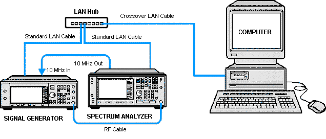
Connect
the equipment to a computer using one of the following methods for instrument control:
-
LAN
Network— connect
the signal generator, arbitrary waveform generator, analyzer, and
computer to an external LAN network using standard LAN cables.
connect
the signal generator, arbitrary waveform generator, analyzer, and
computer to an external LAN network using standard LAN cables.
|
Equipment Setup
|
|
|
|
Equipment
Required
|
-
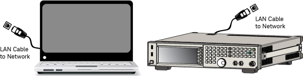
Crossover
LAN—connect
the signal generator directly to the computer using a crossover LAN cable.
(You will need to configure your PC using this setup.)
|
Equipment Setup
|
|

|
|
Equipment
Required
|
-
Crossover
LAN—If connecting
more than one instrument (signal generator, analyzer, arbitrary waveform
generator):
-
GPIB—connect
the signal generator, or signal analyzer directly
to the computer using a GPIB cable.
|
Equipment Setup
|
|

|
|
Equipment
Required
|
You can test the GPIB connections by using either
the Connection Expert or the Interactive IO utility
that comes with the Keysight IO Libraries. Refer to
the Keysight IO Libraries Suite documentation for more information.
-
PXI (M9330A or N6030A only)—connect the computer's MXI/PXI
adapter to the PXI mainframe.
Hardware Connections
The N7621B Signal Studio for Multitone Distortion software supports three general
system configurations. Each system requires an PSG/MXG/EXG/ESG vector signal generator,
an arbitrary waveform generator (AWG), and a spectrum or signal analyzer.
The three systems are designed around the modulation capabilities of the PSG/MXG/EXG/ESG vector signal generators and are:
-
Internal I/Q –
Uses the PSG/MXG/EXG/ESG with internal AWG.
-
External I/Q –
Uses the PSG/MXG/EXG/ESG external I/Q, and external AWG.
-
Wideband I/Q –
Uses the PSG with a wideband I/Q option (015, 016, H16) and an external
AWG.
The following hardware can be used to create a system:
|
|
PSG Series
|
|
E8267C
|
|
E8267C Option 015
|
|
E8267D
|
|
E8267D Option 015
|
|
E8267D Option H16
|
|
X-Series
|
|
N5182A MXG
|
|
N5172B EXG
|
|
N5182B MXG
|
|
ESG Series
|
|
E4438C
|
|
LXI Series
|
|
N8212A
|
|
N8212A Option 016
|
|
|
PSG/ESG Internal AWG (Options 001, 002, 601, or 602)
|
|
MXG Internal AWG (Options 651, 652, 654, 656, or 657)
|
|
EXG Internal AWG (Options 653 or 655)
|
|
M8190A Arbitrary Waveform Generator
|
|
N603xA Arbitrary Waveform Generator
|
|
N824xA
Arbitrary Waveform Generator (Option SL1 is not
supported by this application.)
|
|
M933xA
Arbitrary Waveform Generator
|
|
|
XA-Series
|
|
N9010A EXA
Signal Analyzer
|
|
N9020A MXA Signal Analyzer
|
|
N9030A PXA Signal Analyzer
|
|
N9010B EXA
Signal Analyzer
|
|
N9020B MXA Signal Analyzer
|
|
N9030B PXA Signal Analyzer
|
|
N9040B UXA Signal Analyzer
|
|
SA-Series
|
|
|
E440xA ESA Spectrum Analyzer
|
|
|
E444xA PSA Spectrum Analyzer
|
|
|
|
N8201A Option H02 Down Converter
|
Common 10 MHz Reference
In all configurations the hardware must
share a common 10 MHz reference.
This reference can be provided by the signal generator, the spectrum/signal
analyzer, or by a house standard. The N7621B software always configures
the external arbitrary waveform generator to use an external 10 MHz reference.
The PSG/MXG/EXG/ESG signal generator has an auto sensing 10 MHz reference input.
That is to say, the signal generator will automatically use an external
reference if one is connected. The software verifies a common 10 MHz reference
during a correction measurement or during the self test.
Possible System Configurations
In configurations that use an MXA/PXA signal analyzer, the N7621B Signal Studio for Multitone Distortion software turns off the signal analyzer's Auto Align feature to prevent the possibility of long communication delays during alignment. This is the recommended setting while the Multitone Distortion software is running. If you need to align your MXA/PXA, you can perform a manual alignment (Align Now), but understand that the software cannot communicate with the instrument during the alignment.
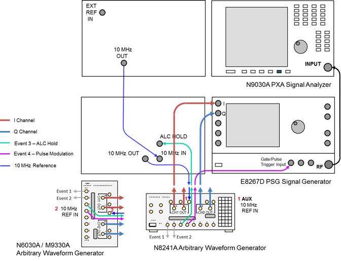
PSG Signal Generator with Wideband IQ option (015,016,H16,HBQ) and an external Arb (N824xA, M933xA, N603xA, M8190A)
Wideband IQ: E8267D PSG Option 016 and M8190A Arb with N9030A PXA
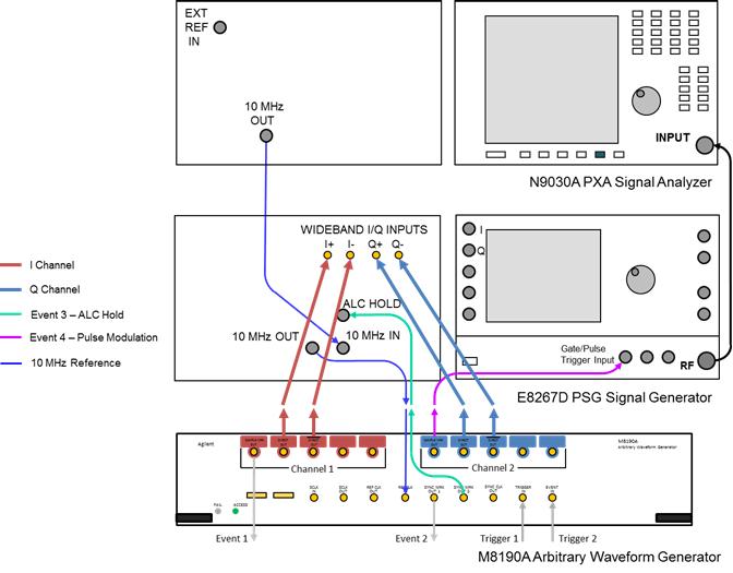
Connections:
-
M8190A Channel 1+ Direct Out to the PSG Wideband I input
-
M8190A Channel 1– Direct Out to the PSG Wideband I– input
-
M8190A Channel 2+ Direct Out to the PSG Wideband Q input
-
M8190A Channel 2– Direct Out to the PSG Wideband Q– input
-
M8190A Channel 2 Sample Mrk Out to the PSG Gate/Pulse/Trigger
input
-
M8190A Sync Mrk Out 2 to the PSG ALC Hold Input (E8267D
only)
-
PXA 10 MHz reference output to the PSG 10 MHz input
-
PSG 10 MHz output to the M8190A 10 MHz reference clock
input
-
PSG RF output to the PXA RF input
Wideband IQ: E8267D PSG Option 016 and N8241A or N6030A Arb with PXA
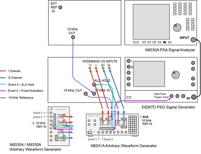
Connections:
-
N8241A Channel 1+ output to the PSG Wideband I input
-
N8241A Channel 1– output to the PSG Wideband I– input
-
N8241A Channel 2+ output to the PSG Wideband Q input
-
N8241A Channel 2– output to the PSG Wideband Q– input
-
N8241A Marker 4 output to the PSG Gate/Pulse/Trigger
input
-
N8241A Marker 3 output to the PSG ALC Hold Input (E8267D
only)
-
PXA 10 MHz reference output to the PSG 10 MHz input
-
PSG 10 MHz output to the N8241A 10 MHz reference
input
-
PSG RF output to the PXA RF input
OR
-
N6030A Channel 1+ output to the PSG Wideband I+ input
-
N6030A Channel 1– output to the PSG Wideband I– input
-
N6030A Channel 2+ output to the PSG Wideband Q+ input
-
N6030A Channel 2– output to the PSG Wideband Q– input
-
N6030A Marker 4 output to the PSG Gate/Pulse/Trigger
input
-
N6030A Marker 3 output to the PSG ALC Hold Input
-
PXA 10 MHz reference output to the PSG 10 MHz input
-
PSG 10 MHz output to the N6030A 10 MHz reference
input
-
PSG RF output to the PXA RF input
Wideband IQ: E8267D PSG Option 016, H16 or HBQ, and N8241A or N6030A Arb with PSA
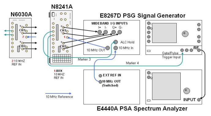
Connections:
-
N8241A Channel 1+ output to the PSG Wideband I input
-
N8241A Channel 1– output to the PSG Wideband I– input
-
N8241A Channel 2+ output to the PSG Wideband Q input
-
N8241A Channel 2– output to the PSG Wideband Q– input
-
N8241A Marker 4 output to the PSG Gate/Pulse/Trigger
input
-
N8241A Marker 3 output to the PSG ALC Hold Input (E8267D
only)
-
PSA/ESA 10 MHz reference output to the PSG 10 MHz input
-
PSG 10 MHz reference output to the N8241A 10 MHz reference
input
-
PSG RF output to the PSA/ESA RF input
OR
-
N6030A Channel 1+ output to the PSG Wideband I+ input
-
N6030A Channel 1– output to the PSG Wideband I– input
-
N6030A Channel 2+ output to the PSG Wideband Q+ input
-
N6030A Channel 2– output to the PSG Wideband Q– input
-
N6030A Marker 4 output to the PSG Gate/Pulse/Trigger
input
-
N6030A Marker 3 output to the PSG ALC Hold Input
-
PSA/ESA 10 MHz reference output to the PSG 10 MHz input
-
PSG 10 MHz reference output to the N6030A 10 MHz reference
input
-
PSG RF output to the PSA/ESA RF input
Wideband IQ: E8267C/D PSG Option 015 and N8241A or N6030A Arb with PSA
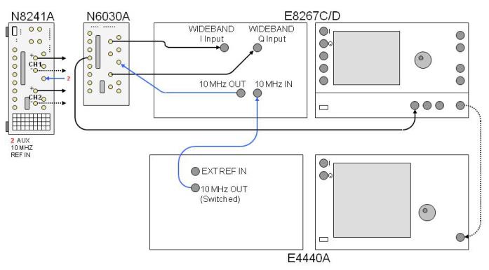
Be sure to enable the spectrum analyzer
10 MHz reference output.
Connections:
-
N8241A Channel 1+ output to the PSG Wideband I input
-
N8241A Channel 2+ output to the PSG Wideband Q input
-
N8241A Marker 4 output to the PSG Gate/Pulse/Trigger
input
-
N8241A Marker 3 output to the PSG ALC Hold Input (E8267D
only)
-
PSA/ESA 10 MHz reference output to the PSG 10 MHz input
-
PSG 10 MHz reference output to the N8241A 10 MHz reference
input
-
PSG RF output to the PSA/ESA RF input
OR
-
N6030A Channel 1+ output to the PSG I input
-
N6030A Channel 2+ output to the PSG Q input
-
N6030A Marker 4 output to the PSG Gate/Pulse/Trigger
Input
-
N6030A Marker 3 output to the PSG ALC Hold Input (E8267D
only)
-
PSA/ESA 10 MHz reference output to the N6030A 10 MHz
reference input
-
PSG RF output to the PSA/ESA RF input
Wideband IQ: N8212A Option 016 and N8241A Arb with PSA
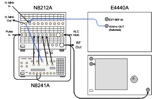
Be sure to enable the spectrum analyzer
10 MHz reference output.
-
N8241A Channel 1+ output to the N8212A Wideband I+ input
-
N8241A Channel 1–
output to the N8212A Wideband I–
input
-
N8241A Channel 2+ output to the N8212A Wideband Q+ input
-
N8241A Channel 2–
output to the N8212A Wideband Q–
input
-
N8241A Marker 4 output to the N8212A Gate/Pulse/Trigger
input
-
N8241A Marker 3 output to the N8212A ALC Hold Input
-
PSA/ESA 10 MHz reference output to the N8212A 10 MHz
input
-
N8212A 10 MHz reference output to the N8241A 10 MHz
reference input
-
N8212A RF output to the PSA/ESA RF input
Wideband IQ: N8212A Option 016 and N8241A Arb with N8201A
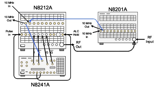
Be sure to enable the spectrum analyzer
10 MHz reference output.
-
N8241A Channel 1+ output to the N8212A Wideband I+ input
-
N8241A Channel 1–
output to the N8212A Wideband I–
input
-
N8241A Channel 2+ output to the N8212A Wideband Q+ input
-
N8241A Channel 2–
output to the N8212A Wideband Q–
input
-
N8241A Marker 4 output to the N8212A Gate/Pulse/Trigger
input
-
N8241A Marker 3 output to the N8212A ALC Hold Input
-
N8201A 10 MHz reference output to the N8212A 10 MHz
input
-
N8212A 10 MHz reference output to the N8241A 10 MHz
reference input
-
N8212A RF output to the N8201A RF input
Signal Generator with external IQ and an external Arb (N824xA, M933xA, N603xA, M8190A)
External IQ: E8267C/D PSG and N8241A or N6030A Arb with PXA
Be sure to enable the spectrum analyzer
10 MHz reference output.
Connections:
-
N8241A Channel 1+ output to the PSG I input
-
N8241A Channel 2+ output to the PSG Q input
-
N8241A Marker 4 output to the PSG Gate/Pulse/Trigger
input
-
N8241A Marker 3 output to the PSG ALC Hold Input (E8267D
only)
-
PXA 10 MHz output to the PSG 10 MHz input
-
PSG 10 MHz output to the N8241A 10 MHz reference
input
-
PSG RF output to the PXA RF input
OR
-
N6030A Channel 1+ output to the PSG I input
-
N6030A Channel 2+ output to the PSG Q input
-
N6030A Marker 4 output to the PSG Gate/Pulse/Trigger
Input
-
N6030A Marker 3 output to the PSG ALC Hold Input (E8267D
only)
-
PXA 10 MHz output to the PSG 10 MHz
input
-
PSG 10 MHz output to the N6030A 10 MHz
reference input
-
PSG RF output to the PXA RF input
External IQ: N5182B MXG and N8241A or N6030A Arb with PXA
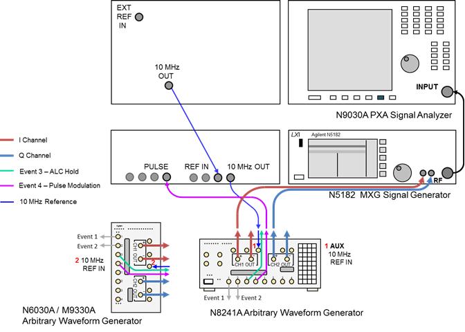
Be sure to enable the spectrum analyzer
10 MHz reference output.
Connections:
-
N8241A Channel 1+ output to the MXG I input
-
N8241A Channel 2+ output to the MXG Q input
-
N8241A Marker 4 output to the MXG Pulse
input
-
PXA 10 MHz output to the MXG 10 MHz reference input
-
MXG 10 MHz output to the N8241A 10 MHz reference
input
-
MXG RF output to the PXA RF input
OR
-
N6030A Channel 1+ output to the MXG I input
-
N6030A Channel 2+ output to the MXG Q input
-
N6030A Marker 4 output to the MXG Pulse
Input
-
PXA 10 MHz output to the MXG 10 MHz
reference input
-
MXG 10 MHz output to the N6030A 10 MHz
reference input
-
MXG RF output to the PXA RF input
External IQ: E8267C/D PSG and N6030A Arb with PSA
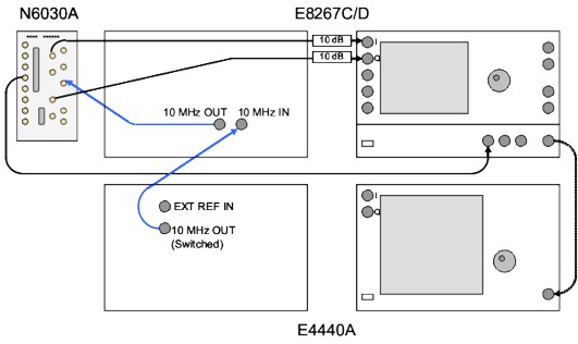
Be sure to enable the spectrum analyzer
10 MHz reference output.
Connections:
-
N6030A Channel 1+ output to the PSG I input
-
N6030A Channel 2+ output to the PSG Q input
-
N6030A Marker 4 output to the PSG Gate/Pulse/Trigger
Input
-
N6030A Marker 3 output to the PSG ALC Hold Input (E8267D
only)
-
PSA/ESA 10 MHz reference output to the N6030A 10 MHz
reference input
-
PSG RF output to the PSA/ESA RF input
External IQ: E4438C ESG and N6030A Arb with PSA
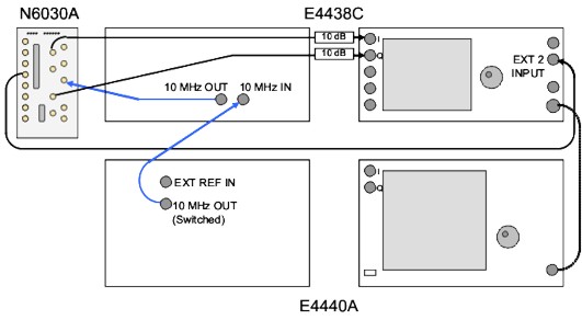
Be sure to enable the spectrum analyzer
10 MHz reference output.
Connections:
-
N6030A Channel 1+ output to the ESG I input
-
N6030A Channel 2+ output to the ESG Q input
-
N6030A Marker 1 output to the ESG External 2 Input
-
PSA/ESA 10 MHz reference output to the N6030A 10 MHz
reference input
-
ESG RF output to the PSA/ESA RF input
Arb only (N824xA, M933xA, N603xA, M8190A)
Arb Only: M8190A with PXA
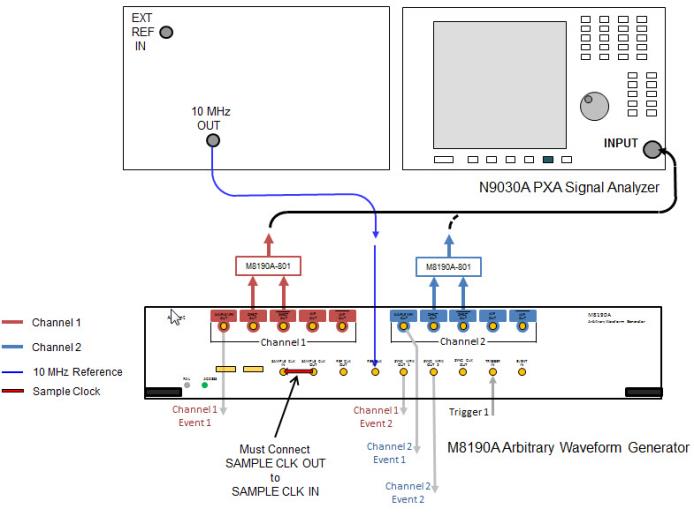
Be sure to enable the spectrum analyzer
10 MHz reference output.
With the N7621B Multitone Distortion software and a dual-channel M8190A, you can select Channel 1, Channel 2, or Both as the active channel.
When both channels are active, the signal is directed to both output channels. Using corrections in this mode is not advised because corrections may not behave as expected.
Connections:
-
M8190A Channel n+ Direct Out to the non-inverting port of the M8190A-801 phase matched balun
-
M8190A Channel n– Direct Out to the inverting port of the M8190A-801 phase matched balun
-
Output of the M8190A-801 balun (labeled "Input" on some balun models) to the PXA RF input
-
M8190A Sample Clock Out to the M8190A Sample Clock In
-
M8190A Channel 2 Sample Mrk Out to the PSG Gate/Pulse/Trigger
input
-
M8190A Sync Mrk Out 2 to the PSG ALC Hold Input (E8267D
only)
-
PXA 10 MHz reference output to the M8190A 10 MHz reference clock
input
Arb Only: N8241A or N6030A with PSA
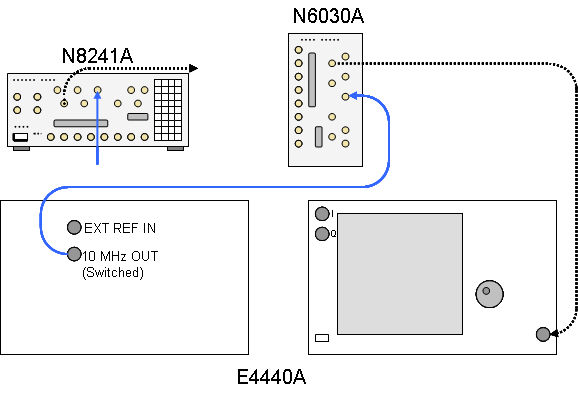
Be sure to enable the spectrum analyzer
10 MHz reference output.
Connections:
N6030A/N8241A Channel 1+ output to the to the PSA RF input
PSA 10 MHz reference output to the N6030A/N8212A 10 MHz input
The N8241 External 10 MHz Reference Input is not supported. Use the
Auxiliary 10 MHz reference input as illustrated above.
Signal Generator with internal Arb (PSG/ESG/MXG/EXG)
Internal IQ: N5182B MXG with MXA or PXA
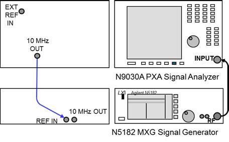
Be sure to enable the spectrum analyzer
10 MHz reference output.
Connections:
The analyzer provides the 10 MHz reference in these configurations.