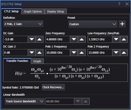
Continuous Time Linear Equalizer Operator
 The Continuous Time Linear Equalizer operator is a transfer function defined by pole frequencies, zero frequencies, and gain values. If you have a device-under-test signal with a closed eye, you can use CTLE to model a circuit that will open the eye.
The Definition: drop-down list lets you select from these types of CTLEs:
-
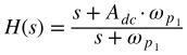
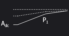
1 Pole — Equation and graph:
-
2 Pole, 1 Zero — Equation and graph:


-
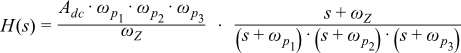
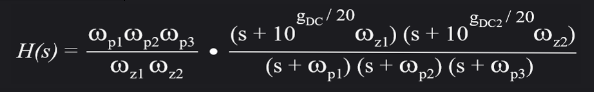
3 Pole, 1 Zero — Equation and graph:

-
3 Pole, 2 Zero — Equation and graph:


-
4 Pole, 1 Zero — Equation and graph:


-
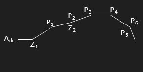
6 Pole, 2 Zero — Equation and graph:

-
2 Pole, AC Gain — Equation and graph:


-
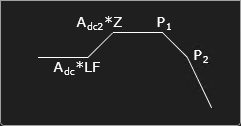
2 Pole, 2 Gain — Equation and graph:

-
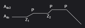
3 Pole, 2 Zero, 2 Gain — Equation and graph:
Once the type of CTLE is selected, fields for entering the CTLE parameter values appear in the dialog box:
- DC Gain (Adc)
- DC Gain (dB) (Adc in dB)
- DC Gain 2 (dB) (Adc2 in dB)
- Zero Frequency (ωZ)
- Zero 1 Frequency (ωZ1)
- Zero 2 Frequency (ωZ2)
- AC Gain (Aac)
- Pole 1 Frequency (ωp1)
- Pole 2 Frequency (ωp2)
- Pole 3 Frequency (ωp3)
- Pole 4 Frequency (ωp4)
- Pole 5 Frequency (ωp5)
- Pole 6 Frequency (ωp6)
- Low-Frequency Zero/Pole (ωLF)
The equation for the selected type of CTLE is shown in the Transfer Function: area.
The symbol rate determined by the selected clock recovery method is shown at the bottom of the dialog box. To change the clock recovery method, click Symbol Rate....
You can also enter the filter's Linear Bandwidth. The Linear Bandwidth controls let you minimize noise gain by rolling off the response above the frequency where there is mostly just noise:
- Manual — If you know at what frequency you want the response to roll off, you can enter it manually in the associated field.
- Track Source Bandwidth — (default) This option simply generates a response up to the bandwidth of the source. For example, if your source is channel 1 and its bandwidth is set to 12 GHz, the response will go to 12 GHz before rolling off. This is the method that maximizes the noise gain.
- Track Tap Spacing — This option forces the response to roll off at a typical ratio of bandwidth to data rate (0.75 x data rate). This will minimize the noise and is best used if you are unsure where in the frequency spectrum the noise is the dominant factor, but would like to minimize the noise gain.
Presets
The Preset controls let you instantly configure the CTLE by selecting the values for a particular specification or saved preset.
To save the current settings as a preset, click the  button. You can save as many presets as you need. The Preset drop-down list shows all of the factory provided presets as well as any that you have created.
If you scroll to the end of the presets drop-down list and click the <Edit List> entry, the Edit CTLE Presets List dialog box opens and lets you reorder, delete, or rename items in the list. In the list, the names of factory provided presets includes the text (factory) which indicates that the entry cannot be edited. Many factory defaults are included in the list.
The Continuous Time Linear Equalizer operator requires a single-valued waveform, as opposed to an eye diagram. Be sure that your trigger setup results in a single-valued waveform at the input to this operator.
Jitter measurements can be made on the output waveform.
Graph Options
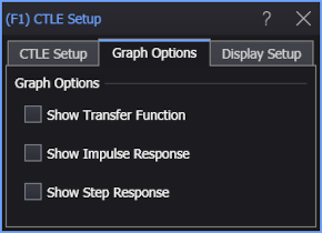
The Show Transfer Function, Show Impulse Response, or Show Step Response options automatically load the operator's network into Freq-Mag, Impulse Response, or Step Response chart windows (like you can do with de-embedding transfer functions — see S-Parameter/Transfer Function Viewer).
Display Setup
Use the Display Setup settings to control the display of the CTLE operator's output waveform, including turning the display on or off. Use the Name field to display an identifying name to the waveform which can be helpful for screen captures or when multiple waveforms are displayed. The settings also include the output waveform's color, scaling, and signal type. The scaling Automatic selection allows the output waveform to track changes to the scaling of the input waveform. This is the setting that you would normally want to use.
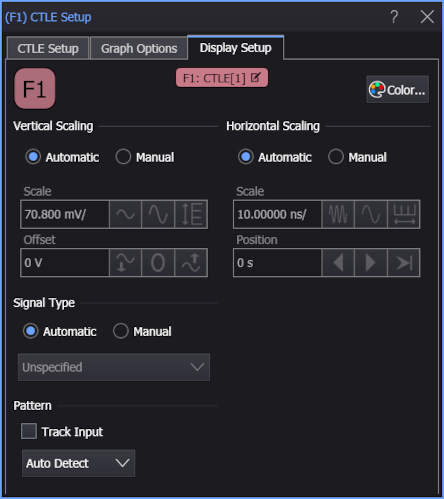
The signal Pattern can be used for BER (Bit Error Ratio), SNDR (Signal to Noise and Distortion Ratio), and other measurements. You can specify the math function has the same pattern as the input waveform (Track Input), Auto Detect the pattern, choose a Known Pattern from a list, or specify your own pattern using a Pattern File.