Linear Equalizer Operator
 The Linear Feedforward Equalizer (LFE) operator allows you to design and apply a finite digital impulse response (non-recursive) filter. You can adjust equalizer settings such as the number of taps, tap gains, tap delay, and bandwidth. With the Linear Feedforward Equalizer, you can model equalizer designs on an actual signal before designing any hardware.
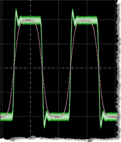
In the figure, the input channel is identified by the green waveform, and the red waveform is the output function from the equalizer.
The Linear Feedforward Equalizer operator requires a single-valued waveform, as opposed to an eye diagram. Be sure that your trigger setup results in a single-valued waveform at the input to this operator.
Jitter measurements can be made on the Linear Feedforward Equalizer's output waveform.
Configuring the Operator
Before you configure the filter, in the diagram drag an output function color to your filter. This will allow you to simultaneously view the input and output waveforms as you develop your filter.
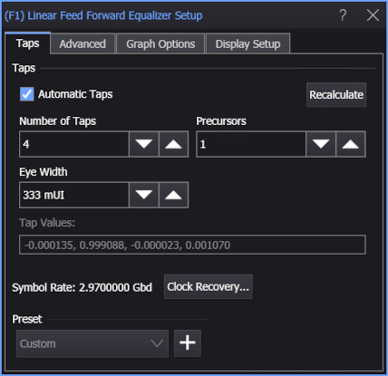
Click on the operator to open the Linear Feed Forward Equalizer Setup dialog box. Normally, Automatic Taps is selected, and you can enter the Number of Taps and Precursors that you want. Tap values are automatically generated. Enter your filter tap values in the Tap Values: entry field. Separate each value using a comma, space, or semicolon. Increasing the number of taps in your model increases the fidelity of the filter's frequency response as compared to an ideal response.
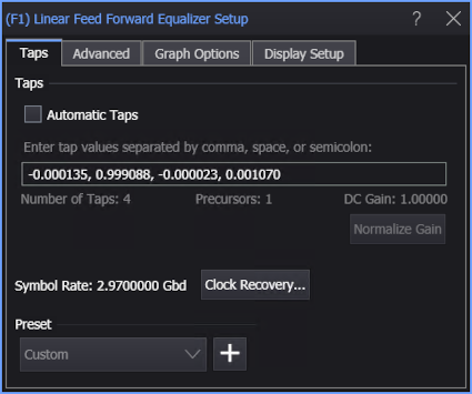
Select Automatic Taps to automatically enter the optimum tap values to open an eye diagram. Click Normalize Gain to automatically adjust the tap values for a maximum equalizer gain of 0 dB (unity). The relative contributions of the tap values are maintained.
| Auto Taps | |
|---|---|
| On | Off |
|
|
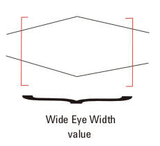
Eye Width specifies the percentage of the unit interval, centered on the clock location, to optimize taps for.
You can enter values from zero to one. For example, if the eye width is set to zero (0), taps are optimized for only the voltage specifically at the clock location of each unit interval. If the eye width is set to 0.2, taps are optimized for the voltage in 20% of the unit interval centered on the clock location. If the eye width is set to one (1), taps are optimized for voltage in the entire unit interval.
Typically with FFE, the receiver samples data not only at the location of the clock, but also in its vicinity. The default is set to 0.333 UI (unit interval) to account for this variance in the sample location. Typically values between 0.0 UI - 0.5 UI are the most useful.
If you are unsure about what value to enter here, but do not want to use the default, think about whether you have more margin vertically or horizontally (where is your uncertainty?). If you optimize the tap values for a narrow portion of the unit interval, your eye will have a greater peak, but only near its center.
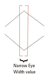
If you optimize the tap values for more of the unit interval, your eye will not be peaked as high, but will be more spread out horizontally.
Preset
Presets allow you to save your dialog box settings to a setup file. Recall a preset to instantly configure your Linear Feedforward Equalizer to your specification. You can save as many presets as you need. If you scroll to the end of the list and click the <Edit List> entry, the Edit LFFE Presets List dialog box opens which allows you to reorder, delete, or rename items in the list.
- To save your settings, click the
 button.
 - To recall your settings, click Load.
The default user data folder for presets files is \Presets\FFE.
Advanced Settings
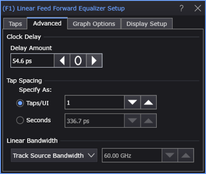
In the Advanced tab, You have these controls:
-
Clock Delay — Equalization may cause your eye diagram to drift so the clock is no longer centered on the eye. When Automatic Taps is not selected, the Delay Amount field lets you specify this shift in order for the eye to be brought back to its original location relative to the unequalized signal.
When Automatic Taps is selected and you run Recalculate, the clock delay is automatically found and set.
This setting is particularly important when explicit clock recovery is used because of the clock relationship to the signal. While the delay moves the real-time eye, it does not change the clock eye relationship.
-
Tap Spacing — When the Automatic Taps setting is cleared, you can specify tap spacing in Seconds. Otherwise, tap spacing is specified in Taps/UI.
-
Linear Bandwidth — The Linear Bandwidth controls let you minimize noise gain by rolling off the filter response above the frequency where there is mostly just noise:
- Manual — If you know at what frequency you want the response to roll off, you can enter it manually in the associated field.
- Track Source Bandwidth — (default) This option simply generates a response up to the bandwidth of the source. For example, if your source is channel 1 and its bandwidth is set to 12 GHz, the response will go to 12 GHz before rolling off. This is the method that maximizes the noise gain.
- Track Tap Spacing — This option forces the response to roll off at a typical ratio of bandwidth to data rate (0.75 x data rate). This will minimize the noise and is best used if you are unsure where in the frequency spectrum the noise is the dominant factor, but would like to minimize the noise gain.
The following figure shows the signal path from the selected input waveform, through the digital equalizer filter, and into the displayed output waveform. If you specify that the tap delay tracks the symbol rate, sampling point values in the input array are used directly as equalizer inputs. If a custom tap delay is selected, equalizer input values may be interpolated.
Graph Options
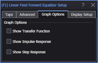
The Show Transfer Function, Show Impulse Response, or Show Step Response options automatically load the operator's network into Freq-Mag, Impulse Response, or Step Response chart windows (like you can do with de-embedding transfer functions — see S-Parameter/Transfer Function Viewer).
Display Setup
Each operator's setup includes a Setup section that has the selections that are shown in the following generic setup dialog box. Use these settings to control the display of the operator's output waveform, including turning the display on or off. Use the Name field to display an identifying name to the waveform which can be helpful for screen captures or when multiple waveforms are displayed. The settings also include the output waveform's color, scaling, and signal type. The scaling Automatic selection allows the output waveform to track changes to the scaling of the input waveform. This is the setting that you would normally want to use.
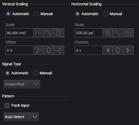
The signal Pattern can be used for BER (Bit Error Ratio), SNDR (Signal to Noise and Distortion Ratio), and other measurements. You can specify the math function has the same pattern as the input waveform (Track Input), Auto Detect the pattern, choose a Known Pattern from a list, or specify your own pattern using a Pattern File.