Setting Up a Network
Use the De-Embedding Network Setup dialog box to create de-embedding networks for your test setup.
First, select one of the preset configurations, such as Relocate the observation node of a measurement. See Preset Configurations.
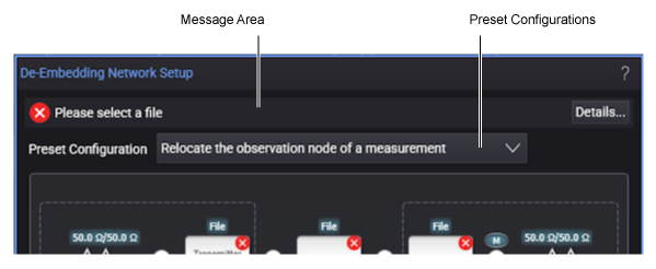
When a preset configuration is selected, its network diagram (containing the blocks, nodes, and legend) is displayed in the De-Embedding Network Setup dialog box.
The network diagrams are interactive. You simply click on the diagram's different blocks and nodes to configure the network. Network diagrams include several definition blocks as shown in the following representative diagram.
Click on the blocks in this picture!
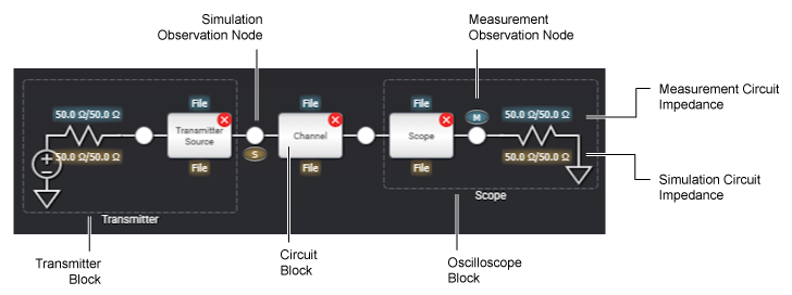
The network diagram has different blocks depending on the selected preset configuration. See Blocks in Network Diagrams.
The network diagram also has nodes that can be selected as the Simulation or Measurement Observation Node. In some preset configurations, nodes can be selected as a Simulation Observation Node only. See Observation Node.
When you select a circuit block in the network diagram, a Setup dialog box appears that lets you define the measurement and simulation circuits for the block. See Circuit Types for Blocks.
After you are done specifying all the appropriate blocks in the network diagram, click Save As... to create a correction transfer function file for your newly configured network (see Correction Transfer Function Files). When create a correction transfer function, you may sometimes receive a warning or error message. These messages are described in Transform Function Messages.
You must save your network test setup as a correction transfer function file before you can use it for measurements.
| Symbol | Description |
|---|---|

|
Indicates a measurement observation node that models the actual physical electrical circuit that produces the measured waveform. |

|
Indicates a simulated observation node that models a hypothetical electrical circuit that exhibits the electrical characteristics that you wish to measure. |

|
Click on a white observation node to open the Observation Node Setup dialog box. Depending on the nodes position in the diagram, you can define it as a measurement node, simulation node, or both. |

|
A dark gray observation node cannot be defined as a measurement or simulation node |

|
A blue text field identifies a measurement circuit block's type. In this example, an S-parameter file. |

|
A bronze text field identifies a simulation circuit block's type. In this example, an S-parameter file. |
|
|
Indicates that a block that needs configuring to be complete. |