Remove S2P Operator
 Use the Remove S2P function to remove the effects of a two-port element from your measurements. This operator is easier to set up than the DeEmbedding operator, however the measurement accuracy is reduced. Before you can use this operator, you must create an S-parameter file of the device to be removed. Import 2-port S-Parameter file into this operator (filename extension of .s2p).
The Deconvolution Setup dialog box has several options to compensate for noise effects as well.
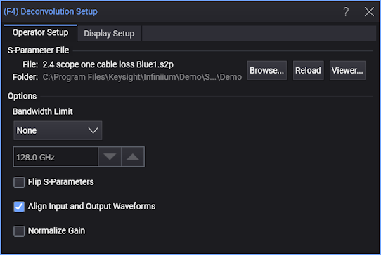
Options
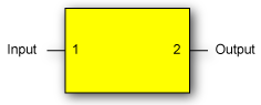
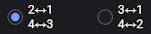
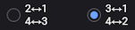
Select the Flip S-parameters field to compensate for reversed port numbering in the file. That is, select this option if the file's S-parameter data is not defined with the ports located as shown in the following diagram, This ensures that the S-parameter order is properly interpreted.
Clear the Align Input and Output Waveforms field to view the delay introduced by your device. By default, this field is normally selected and the input and output waveforms are aligned.
Select Normalize Gain to remove any DC gain when removing s2p.
Click Viewer... to open the S-Parameter/Transfer Function Viewer where you can chart S-parameter and transfer function responses.
Extracting 2-Port Data from a 4-Port S-Parameter File
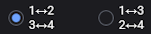
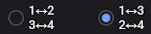
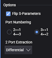 It is possible to import data from a 4-port S-parameter file (.s4p). After you open a 4-port S-parameter file, two additional dialog box fields appear that configure how 2-port information is extracted from the file. These fields are Port Numbering and 2 Port Extraction and they are shown in this figure. In the following table, locate the illustration in the first column that matches how the ports are numbered in your device and the corresponding S-Parameter file. The columns in the row show the settings required to properly extract and interpret the required 2-port information.
| Port Configuration in s4p File | Flip S-Parameters | Port Numbering Options |
2 Port Extraction Options |
|---|---|---|---|
|
|
|
Differential Common Mode Ports 1⇔2 Ports 3⇔4 |
|
|
|
Differential Common Mode Ports 1⇔3 Ports 2⇔4 |
|

|
|
Differential Common Mode Ports 2⇔1 Ports 4⇔3 |
|
|
|
Differential Common Mode Ports 3⇔1 Ports 4⇔2 |
2 Port Extraction Options
The 2 Port Extraction drop-down list selects how to extract a 2-port model from the 4-port S-parameter file and use it in your 2-port transformation.
For example, if you select 1⇔2 and 3⇔4 for the Port Numbering field, you have the following choices:
-
Differential — This means you are extracting port D1 and port D2 of a mixed-mode view of the file (differential path through the 4-port file).
-
Common Mode — This means you are extracting port C1 and port C2 of a mixed-mode view of the file (common-mode path through the 4-port file).
-
Ports 1⇔2 — This means you are extracting only the port 1 and 2 information from the 4-port S-parameter file (one single-ended path through the differential model).
-
Ports 3⇔4 — This means you are extracting only the port 3 and 4 information from the 4-port S-parameter file (the other single-ended path through the differential model).
This operator requires a single-valued waveform, as opposed to an eye diagram. Be sure that your trigger setup results in a single-valued waveform at the input to this operator.
The convolution process used by this operator requires that the measurement circuit and the simulation circuit be linear and time-invariant (small-signal analysis requirements).
Jitter measurements can be made on the Remove S2P operator's output waveform.
To Configure the Operator
- Drag the operator into the construction area.
- Click on the operator to open the Deconvolution Setup dialog box. The dialog box's message prompts you to open a 2-port S-parameter file for your device. You can also open a 4-port device, although the required dialog-box options are more entailed..
- Click Browse to locate the S-parameter file for your device.
- Set the options as described at the beginning of this topic.
- Close the dialog box.
Display Setup
Each operator's setup includes a Setup section that has the selections that are shown in the following generic setup dialog box. Use these settings to control the display of the operator's output waveform, including turning the display on or off. Use the Name field to display an identifying name to the waveform which can be helpful for screen captures or when multiple waveforms are displayed. The settings also include the output waveform's color, scaling, and signal type. The scaling Automatic selection allows the output waveform to track changes to the scaling of the input waveform. This is the setting that you would normally want to use.
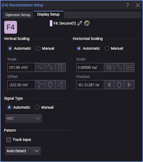
The signal Pattern can be used for BER (Bit Error Ratio), SNDR (Signal to Noise and Distortion Ratio), and other measurements. You can specify the math function has the same pattern as the input waveform (Track Input), Auto Detect the pattern, choose a Known Pattern from a list, or specify your own pattern using a Pattern File.