Deembedding
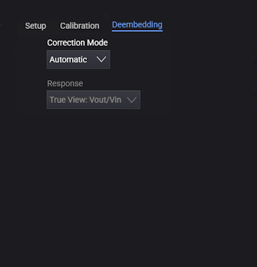
In the Deembedding tab on the lower right portion of the Probes/External Hardware Setup dialog box, you have these controls:
-
Correction Mode — Use this drop-down list to select between Remove Probe/Cable and Off.
-
Off — No correction is performed for the probe/cable.
-
Automatic — When a probe contains an S-parameter description of its own electrical characteristics, as with InfiniiMax probe amplifiers, the oscilloscope will apply the proper correction for the probe. This is known as factory AC response calibration.
When automatic probe correction cannot be completed, the channel data will have a questionable status with one of the following status reasons:
- No transfer function was available for this probe. Channel data is uncorrected.
- Probe transfer function was invalid. Channel data is uncorrected.
- De-embedding output was too low for this probe. Channel data is uncorrected.
In all three cases, the channel data is still acquired and analyzed, However, the data does not have any probe correction applied. Any downstream analysis such as measurements or functions will also contain the same status.
Beware of analyzing uncorrected data.
These statuses should not occur, and they should be reported to Keysight if they do.
-
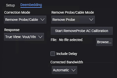
Remove Probe/Cable — Enables the Remove Probe/Cable Mode controls that let you run calibration wizards that measure the proper correction that should be applied for individual probes or cables.
-
-
Remove Probe/Cable Mode — Use this drop-down list to select between:
-
Remove Cable — Choose this option to remove insertion loss caused by cables or fixtures. Click Start RemoveCable AC Calibration to launch the wizard, and follow the step-by-step instructions.
-
Remove Probe — Choose this option for probes. Click Start RemoveProbe AC Calibration to launch the wizard, and follow the step-by-step instructions.
In the last step of the wizard, you identify the probe or cable being calibrated. The calibration results are saved in a file in the %USER_DATA_DIR%\RemoveProbe directory.
Calibration results can be copied from one oscilloscope to another along with probes and cables.
-
-
Browse... — If the calibration has already been performed for your probe/cable, you can click the Browse... button select the file from the Select Remove Probe File dialog box.
-
Corrected Bandwidth — RemoveProbe uses DSP filtering to flatten a probe's frequency response. To compensate for a probe's inherent loss, signals (and noise) are boosted at higher frequencies. The Corrected Bandwidth controls let you change the default boosting limit and filter high-frequency noise:
-
Automatic — RemoveProbe normally sets the bandwidth to a value that has a small amount of boosting in the frequency response.
-
Limit Boosting — Lets you control the maximum amount of gain applied to the signal. You can select a limit from 3 dB to 12 dB (or the equivalent ratio). The default limit is 6 dB. Higher gains can give you faster signal rise times but can also mean higher noise.
-
Specify Bandwidth — Provides a filter to remove unwanted high-frequency noise.
To evaluate the effects of correction adjustments:
- Look at the measured rise time on signal edges. If increasing the boosting limit does not significantly improve rise times, the adjustment may not be worth the trade-off in increased noise.
- Look at the real-time eye measurements. If eye openings are not significantly improved by adjustments, the adjustments may not be worthwhile.
-
-
Include Delay — Apply the delay imposed by the model to the waveform. This selection will accurately shift the waveform in time according to the model.
-
Show Graphs — When the RemoveCable or RemoveProbe wizard completes, you can select this option to view the correction and analysis graphs in a content window. See Viewing Response Correction Graphs.
-
Response — Use this drop-down list to select how the time domain and frequency domain response is characterized:
-
True View: Vout/Vin — Characterizes the output of the probe as a function of the input at the probe tips. Defining the response this way lets you evaluate the probe's accuracy in reproducing the actual signal present in your system with the probe attached. This correction is what you would see with a real band-limited probe that has finite input impedance.
The oscilloscope corrects the “Vout/Vin” response to be flat with frequency and phase to your defined bandwidth limit. It does not de-embed the loading effects of the probe.
Keysight's probe corrections are typically defined using Vout/Vin.
-
Source Estimate: Vout/Vincident = Vout/Vsrc — This method corrects the probe as “what would be there if the probe were not present”.
One drawback of defining the probe’s response in this manner is that if the probe’s loading causes your circuit to lose some timing or amplitude margin, you probably want to know that when you make a measurement. Vout/Vsrc compensation will hide these effects from you.
However, this method can be effective if probing at the transmitter.
When Vout/Vsrc is selected, the system source impedance is 25 Ohms.
You can learn more about these types of probe response corrections in Keysight Application Note 1491,
 Side-by-Side Comparison of Probing Measurements on High-Speed Signals.
 -