Actual measurement is performed with the desired combinations of calibration and compensation functions. Basically, either Method A or Method B shown in the table below is selected, depending on the position of the calibration reference plane.
|
Calibration reference plane |
Required calibration and compensation |
Position and method |
|
|
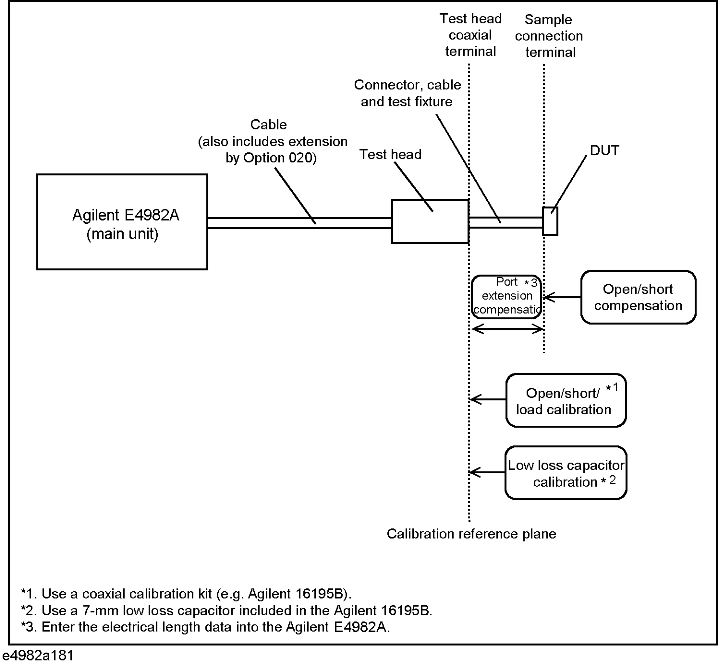
A. Coaxial terminal of test head*1 |
Open/short/load calibration |
For this calibration, connect a coaxial compensation kit*2 to the test head coaxial terminal (used as a calibration reference plane). |
|
|
Low-loss capacitor calibration (only when high-accuracy high-Q measurement or low dissipation factor calibration is required at about 1GHz or more) |
For this calibration, connect a low-loss capacitor to the calibration reference plane.*3 |
||
|
Select the registered Keysight test fixture model number. When you use your customized test fixture, enter the electrical length data from the calibration reference plane through to the sample connection plane. |
|||
|
For this compensation, keep the DUT connection terminal open or shorted out. |
|||
|
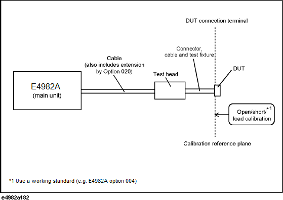
B. DUT connection terminal |
For this calibration, connect a working standard to the DUT connection terminal (used as a calibration reference plane)*4. |
||
*1. Indicates the 3.5-mm terminal of the test head or one equipped with an adapter.
*2. Included in the Keysight 16195B 7-mm calibration kit.
*3. Since the low-loss capacitor is designed as a 7-mm type capacitor, calibration is possible only when the calibration reference plane uses a 7-mm connector.
*4. A reference device valued at the same contour as the DUT. Option 004 (working standard set) or similar can be used.
Calibration and compensation when test head coaxial terminal is used as calibration reference plane.
Calibration when DUT connection terminal is used as calibration reference plane.