The following section describes the procedure to confirm the measurement results of RF power corresponding to the DUT’s DC control/power by using the E5052B’s frequency/power measurement window.
Measurement display indicates a measured value obtained with the power meter if the downconverter is turned off, otherwise a measurement result obtained through the FFT.
To improve readability and reduce search time, few sections of this topic are combined with similar sections from other measurements in Measurement > Common Settings. Links to these new sections are provided in this topic.
Press Trace Next key to select the RF power measurement trace.
If you want to maximize the screen, press the Trace Max key.
The carrier search function is to detect the input signal frequency with the selected carrier frequency band for the downconverter RF IN (i.e. 3 to 10 GHz or 9 to 26.5 GHz) and reflect the result to the nominal frequency. Refer to Executing Carrier Search Function for the setting procedure.
Press Marker to display marker 1 on the screen.
Move marker 1 to the point you want to confirm and read the measurement value displayed in the upper part of the graph. To confirm multiple values, press Marker > Marker x (x=1 to 10), which allows you to display up to marker 10.
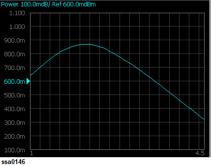
Example of Measurement Screen (RF power characteristics)
By taking into account the transient of DC control/power prior to the sweep, the instrument will start the sweep after the time specified in DC Control > DC Control Delay or DC Power > DC Power Delay has elapsed. This delay time is not included in the sweep time, and it only applies to the first measurement point.