Follow the steps below to measure the phase noise by using the E5052B’s segment phase noise measurement window.
The table below describes the functional differences between the phase noise measurement (PN) and segment phase noise measurement (PS). As for functions other than these, it is the same as the phase noise measurement.
Phase Noise Measurement vs. Segment Phase Noise Measurement
|
Function |
Phase Noise Measurement |
Segment Phase Noise Measurement |
|
Offset Frequency |
Make a Selection |
|
|
Correlation |
Max:10,000 |
Max:200,000 |
|
Sweep Type |
Log |
Linear |
|
RBW Setting |
Disable |
Enable |
In the phase noise measurement (PN), the number of correlation pre-defined depends on the start offset frequency. For example, when the start offset frequency is set to 1 Hz, the correlation of 128000 times is executed in offset frequency of 10 MHz or more. The specification of the phase noise sensitivity in the datasheet is when the start offset frequency is 1 Hz. Refer to Tables as follows to confirm the effect of the start offset frequency on the phase noise sensitivity.
Start offset frequency : 1 Hz
|
Offset |
1 |
47.7 |
190.7 |
1.53k |
12.21k |
97.66k |
781.25k |
6.25M |
|
Number of |
1 |
4 |
32 |
256 |
2048 |
16384 |
32000 |
128000 |
|
Improvement |
0 |
3.0 |
7.5 |
12.0 |
16.6 |
21.1 |
22.5 |
25.5 |
Start offset frequency : 10 Hz
|
Offset |
10 |
190.7 |
1.5k |
12.21k |
97.66k |
781.25k |
6.25M |
|
Number of |
1 |
8 |
64 |
512 |
4096 |
8000 |
32000 |
|
Improvement |
0 |
4.5 |
9.0 |
13.5 |
18.1 |
19.5 |
22.5 |
Start offset frequency : 100 Hz
|
Offset |
100 |
1.5k |
12.21k |
97.66k |
781.25k |
6.25M |
|
Number of |
1 |
8 |
64 |
512 |
1000 |
4000 |
|
Improvement |
0 |
4.5 |
9.0 |
13.5 |
15.0 |
18.0 |
Start offset frequency : 1 kHz
|
Offset |
1k |
12.21k |
97.66k |
781.25k |
6.25M |
|
Number of |
1 |
8 |
64 |
125 |
500 |
|
Improvement |
0 |
4.5 |
9.0 |
10.5 |
13.5 |
In the segment phase noise measurement (PS), pre-defined correlation is not set. Therefore, you need to set the number of correlation with considering pre-defined correlation in the regular mode to obtain enough sensitivity for your application. For more information regarding the correlation settings, see Setting Average Function.
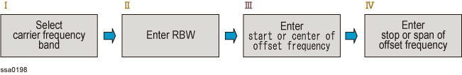
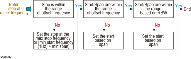
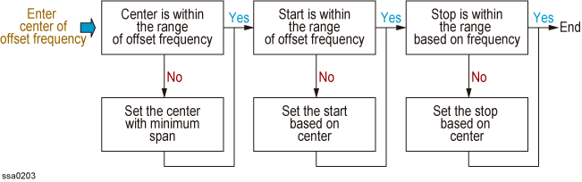
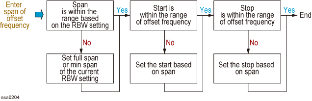
The procedure of selecting the carrier frequency band and setting the offset frequency is shown in the figure below:
Procedure to setup offset frequency
The internal operation after setting the carrier frequency band, RBW and offset frequency is shown in the figure below.
1. Select carrier frequency band
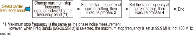
Changing the offset frequency or RBW does not affect the setting of carrier frequency band.
2. Enter RBW
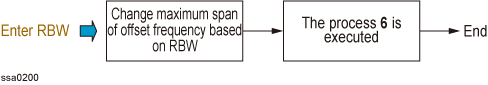
Changing the offset frequency or carrier frequency band does not affect the setting of RBW. The RBW maximum span on the RBW is shown in the table Specifying_Measurement_Resolution_Bandwidth.
3. Enter start of offset frequency
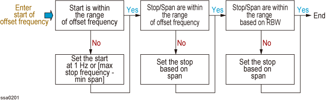
4. Enter stop of offset frequency
5. Enter center of offset frequency
6. Enter span of offset frequency
Press Meas/View > Show Window > Segment PN to toggle ON the segment phase noise measurement.
Press Meas/View > Segment PN to select the segment phase noise measurement window.
You can maximize the segment phase noise measurement window by pressing the Window Max key while the window is selected. You can return to the original size when you press the Window Max key once again.
Press Setup > Capture Range > Normal for PLL method.
Press Setup > Capture Range > Wide for Discriminator method.
If the DUT response is drifting or noisy, SSA cannot lock the signal using PLL method. In such cases, use Discriminator method technique.
The drift should be typically smaller than both of the following limitations.
Normal: 40 kHz/20 msec, 0.4 % of carrier frequency
Wide: 2 MHz/sec, 0.4 % of carrier frequency
PLL and Discriminator are the two types of methods available in E5052B. PLL is the default capture range setting. When Capture Range is Wide, it is possible to measure from 250 MHz. In order to change the frequency range, it is recommended to change the capture range to PLL method.
For more details on PLL method and discriminator method, refer to Overall Instrument Operation.
The switch reference signal option is available in both phase noise measurement and segment phase noise measurement that enables you to select as channel 1 (CH1) and channel 2 (CH2). Normally in both phase noise measurement and segment phase noise measurement, CH1 is set to internal, and CH2 is set to external and then reference signal provided from CH2 is distributed to CH1 internally. For other measurement modes, CH1 is set to internal, and CH2 is set to external.
Follow the steps below to switch reference signal:
Press Meas/View > Segment PN
Press Setup > Reference Oscillator > Bandwidth > Narrow | Wide
The selection of Narrow/Wide is for the Bandwidth of Reference Oscillator of PLL.
Press Setup > Ref. Osc.1 Source > Internal | External
Press Setup > Ref. Osc.2 Source > Internal | External
When reference source is Internal, Internal Oven Controlled Crystal Oscillator signal is used as reference signal.
External input signal is used as reference when the source is External. If E5052B cannot recognize the External input signal, it will automatically select Internal signal as the reference source.
Press Setup > Frequency Band.
Select the appropriate frequency band that contains the target carrier signal from the softkey menu list. The range of each frequency band is listed in the following table.
Selectable frequency bands differ depending on whether the E5053A Microwave Downconverter is used and whether the RF input is direct input or Downconverter input. For setting of downconverter and external mixer, refer to Setting E5053A Microwave Downconverter
|
Carrier Freq. |
Standalone E5052B |
Downconverter: ON |
Downconverter: ON |
Downconverter: ON |
|
10M to 41MHz |
Y |
Y |
N |
Y |
|
39M to 101MHz |
Y |
Y |
N |
Y |
|
99M to 1.5GHz |
Y |
Y |
N |
Y |
|
250M to 3GHz |
N |
Y |
N |
N |
|
250M to 7GHz |
Y |
N |
N |
Y |
|
3G to 10GHz |
N |
N |
Y |
N |
|
9G to 26.5GHz |
N |
N |
Y |
N |
"IF over flow" error may be displayed when segment phase noise is distorted. On the other hand, internal noise level of the instrument may be significant in the measurement display when the DUT has a low-noise characteristics. In this case, follow the steps below to adjust the IF Gain value.
Press Setup > IF Gain.
Enter the IF Gain value in the data entry field that appears in the upper part of the screen.
You can select the value from the options: 0 dB, 10 dB, 20 dB, 30 dB, 40 dB or 50 dB.
The E5052B automatically set PLL BW depending on both the carrier frequency and IF Gain when selecting "Normal" in the capture range. Refer to the table below for the relationship.
IF Gain and PLL BW
|
|
IF Gain is set to either 0 or 10 dB |
IF Gain is set to either 20, 30, 40, or 50 dB |
|
Carrier frequency is less than or equal to 100 MHz |
PLL BW = 1 kHz |
PLL BW = 1 kHz |
|
Carrier frequency is greater than 100 MHz |
PLL BW = 5 kHz |
PLL BW = 350 Hz |
When either “Phase lock loop unlocked” or "IF A/D overflow" error message is displayed, choose an appropriate IF Gain value as indicated in the table below.
IF Gain selection table
|
DUT type |
IF Gain |
|
Frequency drifting sources |
0, 10 dB |
|
Frequency locked sources |
20, 30, 40, 50 dB |
From firmware revision A.3.10, Frequency band, Input Attenuator and IF Gain can be setup to optimum value according to input signal through automatic setting.
Enables when you selected Trigger to Segment PN.
Press Setup > Auto Setting.
Carrier frequency band, Attenuator and IF Gain should be set to optimum value according to input signal.
Auto setting Parameter at each measurement status.
|
Measurement status (PS/Normal(PLL)) |
Freq Band |
Attn |
IF Gain |
|
Downconverter=Off |
Y |
Y |
Y |
|
Downconverter=On, RF Input=E5052B Direct |
Y |
Y |
Y |
|
Downconverter=On, RF Input=Downconverter, Ext.Mixer=Off |
User set |
10dB |
Y |
|
Downconverter=On, RF Input=DownConverter, Ext.Mixer=On |
N |
N |
N |
|
Measurement status (PS/Wide(Discriminator)) |
Freq Band |
Attn |
IF Gain |
|
Downconverter=Off |
Band4 |
Y |
N |
|
Downconverter=On, RF Input=E5052B Direct |
Band4 |
Y |
N |
|
Downconverter=On, RF Input=Downconverter, Ext.Mixer=Off |
User set |
10dB |
N |
|
Downconverter=On, RF Input=DownConverter, Ext.Mixer=On |
N |
N |
N |
When one of the following error messages is displayed, please try to set the wide capture mode (Press Setup > Capture Range > Wide).
"130 Auto setting failed"
"133 Failed to find IF gain"
"132 Try wide capture range"
When "IF A/D overflow" is displayed, please try to decrease 10 dB from the current IF Gain setting (Press Setup > IF Gain).
The auto setting function of the E5052B does not change capture range from the normal capture range to wide capture range automatically. When the carrier frequency is less than 250 MHz or the DUT is noisy (or drifty) while the auto setting is being executed, a message "132 Try wide capture range" is displayed.
Enter the nominal value of the carrier frequency.
Press Setup > Nominal Frequency.
Enter the value of the nominal frequency in the data entry field displayed in the upper part of the screen.
You need to specify nominal frequency only when the downconverter is available.
The carrier search function is to detect the input signal frequency with the selected carrier frequency band for the downconverter RF IN (i.e. 3 to 10 GHz or 9 to 26.5 GHz) and reflect the result to the nominal frequency.
See also Executing Carrier Search Function.
In the SSB segment phase noise measurement of the DUT, LO phase noise characteristics can be selected for optimizing the segment phase noise measurement accuracy.
Press Setup > LO PhNoise Optimize.
Select LO phase noise characteristics in the softkey menu displayed.
LO Phase Noise Characteristics
|
Softkey |
Overview |
|
L(f) for > 150 kHz |
Lowering LO SSB phase noise at > 150 kHz offset frequency |
|
L(f) for < 150 kHz |
Lowering LO SSB phase noise at < 150 kHz offset frequency |
Refer to the Segment Phase Noise Measurement in the Specifications.
Press Start/Center (Stop/Span) > Start.
Enter the sweep start value in the data entry field that appears in the upper part of the screen.
Press Stop/Span (Start/Center) > Stop.
Enter the sweep stop value in the data entry field that appears in the upper part of the screen.
Otherwise, press Start/Center (Stop/Span) > Center to enter the sweep center value in the data entry field that appears in the upper part of the screen and then press Stop/Span (Start/Center) > Span to enter the sweep span value in the same way.
The same softkey will be displayed by pressing either Start/Center or Stop/Span. You can make the same settings by using either of the two keys.
Allowable setting range for the frequency sweep varies depending on whether the E5053A is turned on/off and the RF input is set to 'E5052B Direct'/'Downconverter'.
|
Device Configuration |
Carrier Frequency Bands (Hz) |
Possible Setting Range for Start Frequency (Hz) |
Possible Setting Range for Stop Frequency (Hz) |
|
E5052B is stand-alone, or with downconverter turned off |
10 M to 41 M 39 M to 101 M 99 M to 1.5 G 250 M to 7 G |
1 to 4.999999M 1 to 19.999999M 1 to 39.999999M 1 to 99.999999M |
2 to 5M 2 to 20M 2 to 40M 2 to 100M |
|
With the downconverter turned on and RF input set to 'E5052B Direct' |
10 M to 41 M 39 M to 101 M 99 M to 1.5 G 250 M to 3 G |
1 to 4.999999M 1 to 19.999999M 1 to 39.999999M 1 to 99.999999M |
2 to 5M 2 to 20M 2 to 40M 2 to 100M |
|
With the downconverter turned on and RF input set to 'Downconverter' |
3 G to 10 G 9 G to 26.5 G |
1 to 99.999999M 1 to 99.899999M |
2 to 100M 2 to 99.9M |
Press Avg/BW > RBW
Enter the RBW value in the data entry field that appears in the upper part of the screen.
You can select the value from the options as follows:
Relation between RBW and Span
|
RBW value |
Maximum Span |
Minimum Span |
|
25kHz |
24.43MHz |
1Hz |
|
12.5kHz |
12.215MHz |
1Hz |
|
6.25kHz |
6.1075MHz |
1Hz |
|
3.13kHz |
3.05375MHz |
1Hz |
|
1.56kHz |
1.526875MHz |
1Hz |
|
781Hz |
763.4376kHz |
1Hz |
|
391Hz |
381.7188kHz |
1Hz |
|
195Hz |
190.8594kHz |
1Hz |
|
97.7Hz |
95.4296kHz |
1Hz |
|
48.8Hz |
47.7148kHz |
1Hz |
|
24.4Hz |
23.8574kHz |
1Hz |
|
12.2Hz |
11.9288kHz |
1Hz |
|
6.1Hz |
5.9644kHz |
1Hz |
|
3.05Hz |
2.9822kHz |
1Hz |
|
1.53Hz |
1.491kHz |
1Hz |
|
763mHz |
745.6Hz |
1Hz |
|
381mHz |
372.8Hz |
1Hz |
|
191mHz |
186.4Hz |
1Hz |
|
95.4mHz |
93.2Hz |
1Hz |