Follow the steps below to confirm the results of the DUT’s phase transient measurement by using the E5052B’s transient measurement window.
Press the Trace/Next key to select the phase transient measurement trace. You can confirm which measurement trace is selected by viewing the cursor that is displayed to the left of the trace title.
You can also click on the phase transient measurement trace for confirmation.
The instrument calculates the phase deviation within the Narrow Band measurement range based on the frequency transient (Narrow Band) measurement result. The phase reference function sets the reference value of frequency to calculate the phase transient.
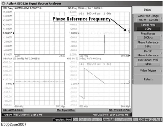
In case the target frequency is equal to the final frequency (the right most measurement data obtained in the frequency transient (Narrow Band) measurement) of the DUT, it can be used as the phase reference frequency. If the target frequency is deviated from the final frequency of the DUT, use the actual frequency measured at the right end of measurement point as set the phase reference frequency. Then the phase data over time starts from zero at the right end of the measurement point, and the phase data maintains as long as the measured frequency stays at the phase reference frequency.
Press Setup > Phase Reference.
Enter the phase reference value, then measure the phase transient data again.
Defining Phase Reference Frequency
Confirming Result of Power Transient Measurement
The phase reference frequency is restricted to the range of Narrow Band measurement that is determined by the target frequency and frequency range.
The Marker -> Phase Reference function automatically sets the phase reference frequency based on the actual frequency data where the active marker is located at the frequency over time trace.
You can set the measurement value of the X-Axis value you specified to the phase reference (phase 0). Follow the steps below.
Press Format > Phase X Reference
Enter the X-Axis value (position) set as the phase reference in the data entry field that appears in the upper part of the screen.
You can also use the marker. Move the marker to the position of the phase reference and press Format > Marker -> Phase X Reference
When you measure the signal with larger trace noise repeatedly, the observed trace may go up and down on the display. This function enables to reduce it. The phase reference position is set at the point where the averaged phase of the specified X span becomes 0. The phase offset is calculated from all of points within the specified X span.
If the specified Phase X Reference is lower than the start point, the start point is set as Phase X Reference.
If the specified Phase X Reference is higher than the stop point, the stop point is set as phase X Reference.
If there are no measurement points in the specified X Reference Span, the averaged phase is calculated to use the interpolated data between the closest both side measurement points.
Follow the steps below.
Press Format > Phase X Reference.
Enter the X-Axis value (position) set as the phase reference in the data entry field that appears in the upper part of the screen.
You can also use the marker. Move the marker to the position of the phase reference and press Format > Marker -> Phase X Reference.
Press Format > X Reference Span.
Enter the span value.
The phase offset is calculated from all of points within the specified X span by the step in the figure below.
Phase X Reference and X Reference Span
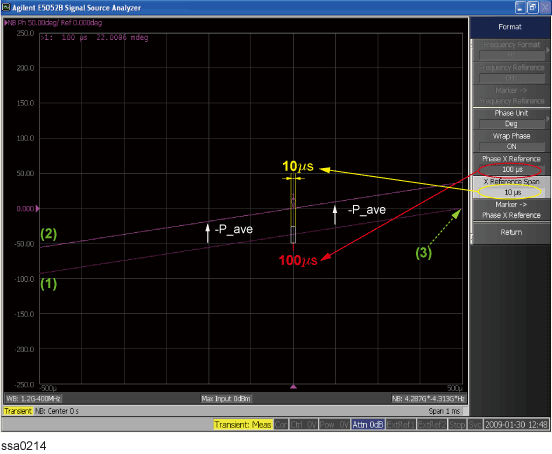
(1) Calculate average phase (P_ave) in the specified range of default curve.
(2) Add offset value (-P_ave) to the default phase curve.
(3) Default phase zero point.
If the actual measured frequency is different from the phase reference frequency you set, the recalc phase reference function also allows you to adjust the baseline of the phase transient data manually after a single measurement.
This function cannot be used when you select Auto Reference to ON.
Press Setup > Recalc Phase Reference.
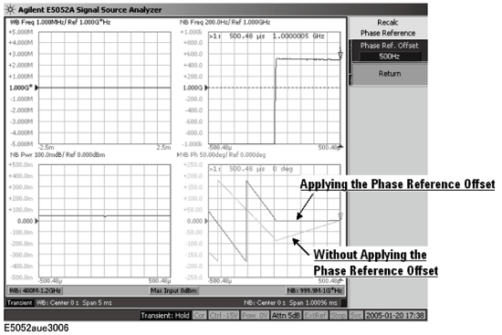
Press Phase Ref. Offset to enter the offset frequency value relative to the phase reference frequency, and then the baseline of the phase transient data will be adjusted.
Using Recalculating Phase Data Function to Adjust Baseline of Phase Transient
This function enables to set the phase reference offset automatically so that the specified point on X-axis becomes a reference position of phase measurement. This function calculates the phase reference offset by following method.
Average the measured frequency data in the specified span by X reference and X span (or N2 X reference and N2 X Span).
Subtract the phase reference frequency (Phase Reference under Setup key) from the averaged frequency value.
Set the phase reference offset at the above subtracted value.
Follow the steps bellow.
Press Setup > Recalc Phase Reference > Auto Reference > ON.
Press X Reference, then enter the X Reference value.
Press X Span, then enter the X Span value.
Follow the steps bellow when you use the Narrow2 band.
Press Setup > N2 Recalc Phase Reference > Auto Reference > ON.
Press N2 X Reference, then enter the X Reference value.
Press N2 X Span, then enter the X Span value.
Phase Reference Offset is specified by the step in the figure below.
Auto Reference : ON
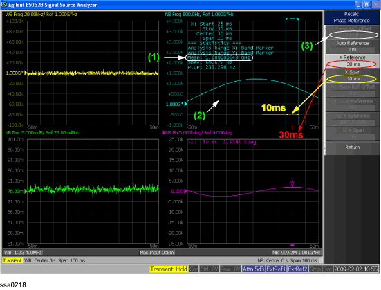
(1) Averaged frequency value
(2) Phase reference frequency
(3) Phase Ref. Offset : (1) - (2)
You can select the unit (phase unit) used in the phase transient measurement trace screen and specify the wrap phase.
Press Format > Phase Unit.
Select the appropriate format from the softkey menu list. You can select any of the three options: Deg, Rad or Grad.
Press Format > Wrap Phase to turn on/off the wrap phase function.
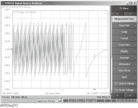
Press Marker to display marker 1 on the screen.
Move marker 1 to the point you want to confirm and read the measurement value displayed in the upper part of the graph. To confirm multiple values, press Marker > Marker x (x=1 to 10), which allows you to display up to marker 10.
Example of Measurement Screen (phase transient)