How to start the DC Source Control dialog
Using Hardkey/SoftTab/Softkey
Using a mouse
Press Sweep > Source Control > DC Source....
Click Stimulus.
Select Sweep.
Select Source Control.
Select DC Source.
![]()
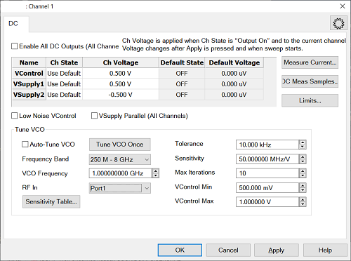
DC Source Control defines the DC output states and voltages of the DC Sources (DC Control, DC Supply1, DC supply2) for each channel. It also allows you to tune VCO frequency.
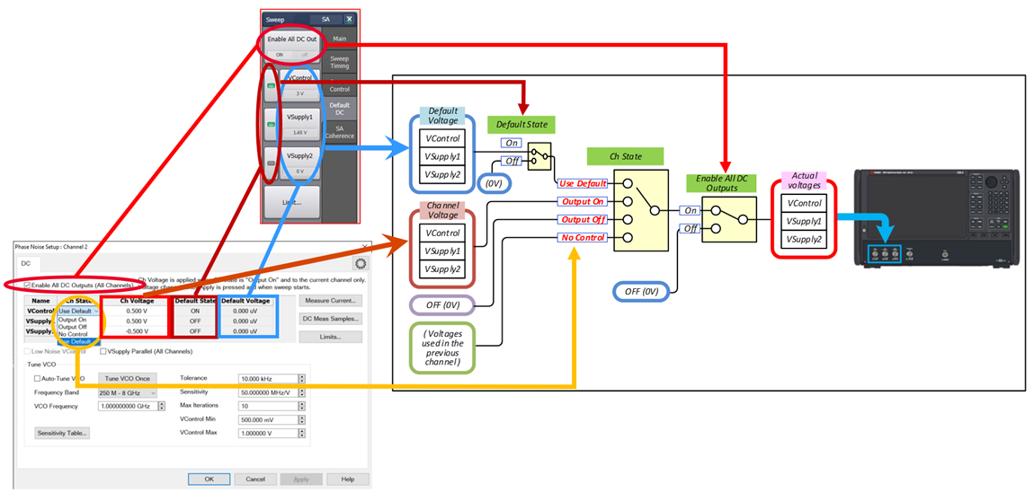
Enable All DC Outputs (All Channel) - Enable/disable all DC outputs for the all channel. The DC voltage is outputted immediately. If the measurement is in progress, it will be aborted. Then, a sweep starts with the new setting. This turned off after recalling the state. This is the same with Enable All DC Out under Sweep > Default DC tab.
Ch State - On/Off for the voltage control for the current channel. Ch State is valid for the current channel only. The setting changes at next sweep after Apply/OK is clicked.
Ch Voltage: Specify the output voltage for each DC output. Ch Voltage is valid when Ch State is “Output On” and for the current channel only. Voltage changes at next sweep after Apply/OK is clicked. Default State: Show the Default DC state. Default Voltage: Show the Default DC voltage setting.
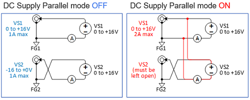
Measure Current - Show the current value for all outputs (VControl/VSupply1/VSupply2). The measurement is made at the click DC Meas Samples: - Set the number of times for current measurement. The averaged data is shown when the Measure Current is clicked. Limits - Specify the output voltage limit for each DC output to protect the DUT. See DC Limit Dialog. Low Noise VControl - Enable the low noise mode for VControl. The measurement speed makes slower. VSupply Parallel - This function inverts DC Supply 2 polarity and connect it to DC Supply 1 in order to double the output current of the DC Supply1 (positive ONLY) . You must leave the DC Supply 2 BNC unconnected (center pin and outer conductor) when using this mode. DC Supply 2 outer conductor will float at VSupply1 voltage, relative to DC Supply 1 outer conductor. When you need negative voltage with parallel mode, invert the center and outer conductor using external wiring. See Caution below Caution for VSupport Parallel: If touching across the outer conductor of DC Supply 1 and DC Supply 2 with parallel mode, this will cause the flow of short current (up to 2.5A).
Tune VCO - Tune the VCO frequency by adjusting VControl voltage to meet the target frequency. Auto-Tune VCO - Tune the VControl voltage continuously before each sweep starts to keep the target frequency Tune VCO Once - Tune the frequency one time at click. Frequency Band - Select the frequency band which include the target VCO frequency. VCO Frequency - Set the target frequency. RF In - Select RF In port (Spectrum Analysis Class only) Tolerance - The maximum desired deviation from the specified target frequency. Sensitivity - The sensitivity of VCO (Hz/Volt). This value is used at the first loop of sequence. When the sensitivity table is defined, this value is not used. Max Iteration - The maximum number of readings to take at each data point for iterating the frequency. VControl Min - The minimum limit of VControl during Auto Tune sequence. VControl Max - The maximum limit of VControl during Auto Tune sequence.
Auto Tune sequence is shown below.
Note: The VCO frequency must be within +/-3 GHz of initial oscillation frequency of the DUT. If the initial oscillation frequency is out of range, The sequence is aborted and shows an error message of "Auto frequency control out of loop." The +/-3 GHz range may become narrower if the frequency is close to system band frequencies, 7 G, 8 G, 21.5 G and 25 GHz.
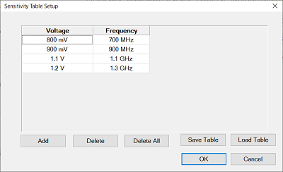
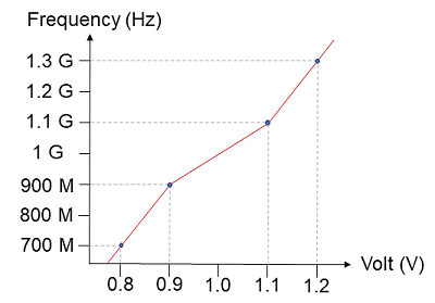
This table allows you to define the sensitivity for Auto-Tune. The sensitivity curves are defined by each points. Interpolation and exploration will be applied as shown as an example below.
Add - Add the row for new point Delete - Delete the selected row Delete All - Clear the table Save Table - Save the table data in .csv format. Load Table - Recall the table data.
|
|||||||||||||||||||||||