You can set the stimulus condition for each channel independently.
Other topics about Setting Measurement Conditions
You can select the sweep type from the following four types.
|
SoftKey |
Description |
|
Linear Freq |
Sweeps frequencies in linear scale. |
|
Log Freq |
Sweeps frequencies in logarithmic scale. There could be a little bit margin of error between the ideal frequency points of the selected sweep type and the real frequency points of measurement. Use Saving Data in CSV Format or SCPI.CALCulate(Ch).SELected.DATA.XAXis command to get the X axis data of actual measurement points. |
|
Segment |
Performs a sweep with linear sweep conditions (segments) combined. For more information, refer to Performing a Segment-by-Segment Sweep (segment sweep). |
|
Power Sweep |
Sweeps power levels in linear scale. |
|
DC Bias Sweep |
Sweeps DC bias levels. This is available only when option is 3L5/3L4/3L3. |
The procedure for selecting the sweep type is as follows:
Press Channel Next (or Channel Prev) to select the channel for which you want to set the sweep type.
Press Sweep Setup > Sweep Type.
Press the desired softkey to select the sweep type.
The time sweep is shown in Measuring in Time Series. This allows you to display the measurement parameter versus time.
There are two ways to set the sweep range: by specifying the lowest and the highest values and by specifying the center value and a span. Once the sweep range is set, it is possible to change the range by substituting the lowest value, the highest value, or the center value with a value (stimulus value) represented by a marker on the trace.
Press Channel Next (or Channel Prev) to select the channel of which sweep range will be set.
Click Start, then input the lowest value.
Click Stop, then input the highest value.
Press Channel Next (or Channel Prev) to select the channel of which sweep range will be set.
Click Center, then input the center value.
Click Span, then input the span value.
In the channel window of which range must be set, place the active marker on the active trace to a position that corresponds to the new range (to the lowest, highest, or center value).
Press Marker Fctn.
Click the softkey that corresponds to each value.
If the reference marker is on and the stimulus value of the active marker is expressed by a value relative to the reference marker, the absolute stimulus value will be used to set the new sweep rang.
You can turn on/off the stimulus signal output, but this prevents you from performing the measurement. Therefore, normally this feature will not be used. This feature is mainly used to turn the output ON back after it has been turned OFF by the power trip feature.
Follow these steps to turn the stimulus signal output on/off:
Press Sweep Setup.
Click Power > RF Out (Each press toggles between on/off).
When set to OFF, "RF OFF" is displayed in Instrument Status Bar.
The power trip is a feature that the instrument uses to automatically turn OFF the output of the stimulus signal to protect the instrument when a signal of which level exceeds the upper limit is inputted to the test port.
If the power output is automatically turned off by the power trip feature, remove the cause of the over-input and turn ON the power output according to the above steps to restart the measurement.
Press Channel Next (or Channel Prev) to select the desired channel.
Press Sweep Setup key.
Click Power > Port Couple, then select the on/off setting of the level coupling for all the ports.
The power level of port 1 is coupled with the power level for all ports.
If you change the on/off setting of the level coupling, all ports are automatically changed to the same level value as that of port 1.
Follow the procedure below according to the Port Couple.
When setting level for all ports (Port Couple ON)
Click Power, then enter the power level.
When setting level for each port (Port Couple OFF)
Press Port Power, then click the softkey corresponding to each port (Port 1 Power, Port 2 Power, LF OUT Power)
Enter the power level.
You can use the power slope feature to correct the attenuation of a power level so that it is simply proportional to the frequency (attenuation due to cables and so on), which improves the accuracy of the level actually applied to the DUT.
Press Channel Next (or Channel Prev) to select the desired channel.
Press Sweep Setup key.
Click Power > Slope [OFF] (Slope [ON]). Each press toggles between on/off.
Press Channel Next (or Channel Prev) to select the desired channel.
Press Sweep Setup key.
Click Power > Slope [xxx dB/GHz] ("xxx" represents the current set value.).
Enter the correction coefficient using the ENTRY block keys on the front panel.
The procedure for setting the fixed frequency (CW frequency) at the power sweep and DC Bias sweep (Option 3L5/3L4/3L3 only) is as follows:
Press Channel Next (or Channel Prev) to select the desired channel.
Press Sweep Setup key.
Click CW Freq, then enter the fixed frequency.
The number of points is the number of data items collected in one sweep. It can be set to any number from 2 to 1601 for each channel independently.
To obtain a higher trace resolution against the stimulus value, choose a larger value for the number of points.
To obtain higher throughput, keep the number of points to a smaller value within an allowable trace resolution.
To obtain higher measurement accuracy after calibration, perform calibration using the same number of points as in actual measurements.
Press Channel Next (or Channel Prev) to select the desired channel.
Press Sweep Setup key.
Click Points, then input the desired number of points.
Sweep time is the time taken to complete a sweep for each stimulus (source) port. Two modes are available for setting the sweep time: manual sweep time mode and automatic sweep time mode.
|
Sweep Time Mode |
Description |
|
Manual |
In this mode, the sweep time is set manually. Once the sweep time is set, changes in the measurement conditions do not affect the sweep time as long as it is within the analyzer's capability. If the sweep time becomes lower than the analyzer's lower sweep time limit, the sweep time is reset to the shortest time within the conditions. If the sweep time exceeds the analyzer's upper sweep time limit, the sweep time is reset to the longest time within the conditions. |
|
Auto (Default) |
The sweep time is always kept to the shortest time possible with the current measurement conditions. |
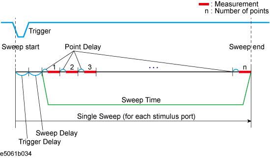
The following figure shows the definitions of the sweep time and the sweep delay time.
Sweep delay is time before starting a sweep for each stimulus (source) port. Sweep time does not include the sweep delay.
When the trigger mode is set at "On Sweep".
When the trigger mode is set at "On Point".
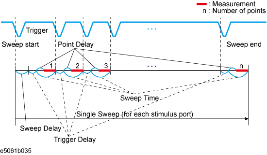
Trigger delay is available when the trigger source is set at external.
Sweep time is the total of point delay and measurement time in all measurement points when the trigger mode set at "On Point".
Press Channel Next (or Channel Prev) to select the desired channel.
Press Sweep Setup > Sweep Delay.
Using the ENTRY block keys on the front panel, input the desired sweep delay time (in seconds).
Press Channel Next (or Channel Prev) to select the desired channel.
Press Sweep Setup > Sweep Time Auto to turn OFF.
The softkey named Sweep Time is activated. Press Sweep Time.
Using the ENTRY block keys on the front panel, input the desired sweep time (in seconds).
The sweep time is not correctly displayed in DC Bias sweep at 90 kHz and above when there are the traces for both Gain-Phase and S-Parameter measurements in one channel.
The following procedure allows you to time sweep and the measurement parameter is displayed versus time.
Press Channel Next (or Channel Prev) to select the channel of which sweep range will be set.
Press Span > 0 > x1 to set the span value to 0 (zero span).
Press Center, then input the desired value (frequency, power, or DC bias).
Press Sweep Setup > Sweep Time Auto to turn OFF.
Press Sweep Time, then input the duration of the sweep which is displayed on X-axis.
Press Marker to display the marker 1. The time at the marker shows as the marker position value at the upper left corner on the screen.