DC Bias Source
DC Monitor
Other topics about General Principles of Operation
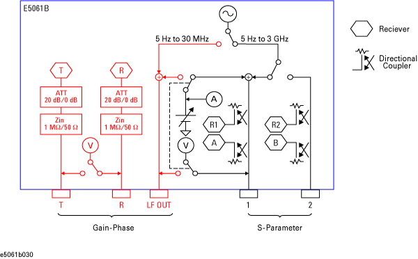
A network analyzer supplies a sweep signal to a DUT, measures its transmission and reflection, and displays the results as ratios against the input signal from the signal source. The E5061B network analyzer consists of the circuit modules shown in the following figure.
System Diagram for the E5061B Network Analyzer (Optoin 3L5/3L4/3L3)
System Diagram for the E5061B Network Analyzer (Besides Option 3L5/3L4/3L3)
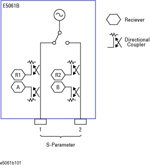
The synthesized source generates a sweep signal in the specified frequency range.
The signal source is phase-locked to a highly reliable quartz crystal oscillator to maintain a high level of accuracy in its frequency as well as to achieve precise phase measurements.
The source switchers are used to switch test ports to which the signal is supplied from the source. The source switcher always set at the port1 in T/R test set option (options 115, 135, 117 and 137)
The signal separator consists of directivity couplers that detect input and output signals at the test ports. On a test port to which a signal is output, the output signal and the reflection from the DUT are detected as the reference signal (R1) and the test signal (A), respectively. On the other ports, the signal that is transmitted through the DUT is detected as the test signal (B). All signals are then sent to the receiver.
Each signal that is sent to the receiver is first converted into an IF signal by a mixer and then converted into a digital signal by an ADC (analog to digital converter). These processes are applied to each signal independently. The digital data is then analyzed by a micro processor and measurement results are displayed on the screen. The receiver R2 is not available in T/R test set option (options 115, 135, 117 and 137)
Built in DC bias source can apply -40 V to +40 V DC on the signal of LF out and Port 1. The switcher for DC bias can be changed independently from the Source switcher.
Voltage and current meters are equipped to monitor DC on received and DC biased source. DC voltage can be measured at LF out, R, T and Port 1. DC current can be measured at LF out and Port 1 .