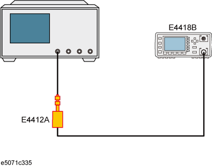
This section shows an example of executing power calibration using the E4418B power meter and the E4412A power sensor.
Power calibration may not be executed when the specified frequency and level is out of range of the power sensor specification.
In this example, power calibration is executed according to the steps shown in table below.
|
Step |
Description |
|
Connects the power meter to the E5071C. |
|
|
Configures the power meter's USB/GPIB interface and GPIB address with the E5071C. |
|
|
Sets conditions such as the power level and frequency. |
|
|
4. Executing Zero Adjustment and Calibration of Power Sensor |
Executes zero adjustment and calibration of the power sensor. |
|
Selects the port, selects the power sensor, sets the number of measurements at one point, and sets the tolerance during power calibration. |
|
|
Connects the power sensor. |
|
|
Executes the measurement of calibration data. |
Connect the GPIB connector on the E4418B (GPIB address: 14) to the E5071C through USB/GPIB Interface.
From Firmware revision 9.2, E5071C supports USB enabled power sensors. When you connect USB enabled power sensor for the first time, new hardware wizard runs. For more information, refer to Setting system controller (USB/GPIB interface)
Follow the steps to select the power meter
|
Setting Description |
Key Operation |
|
USB/GPIB |
System > Misc Setup > Power Meter Setup > Select Type > USB/GPIB |
Follow these steps to configure the power meter's GPIB address.
|
Setting Description |
Key Operation |
|
GPIB address of the power meter: 14 |
System > Misc Setup > GPIB Setup > Power Meter Address > 1 > 4 > x1 |
You can also set the GPIB address of power meter by pressing System > Misc Setup > Power Meter Setup > GPIB Address
Follow these steps to configure the USB power meter
|
Setting Description |
Key Operation |
|
USB power meter |
System > Misc Setup > Power Meter Setup > USB |
Follow these steps to configure the stimulus conditions:
|
Setting Description |
Key Operation |
|
Presetting |
Preset > OK |
|
Sweep type: Power |
Sweep Setup > Sweep Type > Power Sweep |
|
Fixed frequency: 1 GHz |
Sweep Setup > Power > CW Freq > 1 > G/n |
|
Start value: -40 dBm |
Start > +/- > 4 > 0 > x1 |
|
Stop value: -10 dBm |
Stop > +/- > 1 > 0 > x1 |
|
Number of points: 61 |
Sweep Setup > Points > 6 > 1 > x1 |
Execute the zero adjustment and calibration of the power sensor according to the E4418B Power Meter User's Guide.
Follow these steps to set the calibration data measurement conditions:
|
Setting Description |
Key Operation |
|
Selecting the test port: 1 |
Cal > Power Calibration > Select Port > 1 |
|
Selection of power sensor: A |
Cal > Power Calibration > Use Sensor [ A ] |
|
Number of measurements at one measurement point: 4 |
Cal > Power Calibration > Num of Readings > 4 > x1 |
|
Tolerance during power calibration: 5 dB |
Cal > Power Calibration > Tolerance > 5 > x1 |
Connect the power sensor as shown below.

Follow this step to measure the calibration data:
|
Setting Description |
Key Operation |
|
Measuring calibration data |
Cal > Power Calibration > Take Cal Sweep |