Other topics about Frequency Offset Measurement
The E5071C option 008 provides a frequency-offset function and an absolute measurement function.
Generally with network analyzers, the frequency must be the same both at the signal source and at the receiver, so frequency-translating devices such as mixers or converters cannot be measured. To enable the analyzer to measure frequency conversion devices, the receiver frequency must be synchronized with a frequency consisting of the input frequency and a certain added offset, which is called frequency-offset sweep.
The E5071C option 008 provides not only this frequency-offset sweep but state-of-the-art mixer calibration features: vector-mixer calibration and scalar-mixer calibration. Vector-Mixer Calibration allows you to measure the conversion loss, phase, reflection parameter, and group delay of the mixer. Scalar-Mixer Calibration performs high-accuracy measurement for the magnitude and reflection parameter of mixer conversion loss.
Moreover, the E5071C option 008 supports an absolute measurement function. The network analyzers normally measure the ratio of the test signal's magnitude and phase to the reference signal. In contrast, the absolute measurement function performs a measurement of the absolute value of the test signal's magnitude. In combination with the frequency-offset function, the absolute measurement function provides measurements that include measurement of harmonic distortion. It also provides high-accuracy measurement when combined with Power Calibration and Receiver Calibration.
When you measure the 3rd harmonics over 8.5 GHz with options 2D5, 4D5, 2K5 and 4K5, it is recommended to suppress the carrier signal using filter etc before executing the measurement for accurate results.
In mixers and frequency converter devices measurements, you have RF and LO inputs and an IF output. Also appearing from the IF port are several other mixing products of the RF and LO signals. In mixers and frequency converter devices measurements, leakage signals from one mixer port propagate and appear at the other two mixer ports. These unwanted mixing products or leakage signals can cause distortion by mixing with the harmonic of the analyzer’s first down-conversion stage and cause measurement error.
To ensure successful mixer measurements, the following measurement challenges must be taken into consideration:
By choosing test frequencies (frequency list mode), you can reduce the effect of spurious responses on measurements by avoiding frequencies that produce IF signal path distortion. To avoid frequency spacings equal to the analyzer’s IF is an important factor. In the case of the E5071C, the IF is 3 MHz and 3.25 MHz with fundamental mixing under 8.5 GHz measurements, and 3rd harmonic mixing over 8.5 GHz measurements. Therefore, avoid the frequencies which meet the following formula. (*1)
m ×RF ± n×LO = l × E5071C_Local ± 3 MHz or 3.25 MHz (m, n, l = 0, 1, 2 ...)
where, E5071C_Local is
Measured Signal Frequency + 3 MHz or 3.25 MHz (Under 8.5 GHz)
1/3 × (Measured Signa Frequency + 3 MHz or 3.25 MHz) (Over 8.5 GHz)
(*1): Except the target measuring frequency, that is m=n=1
Another effective technique is to reduce the instrument’s IF bandwidth. Reducing the IF bandwidth will more selectively filter signals in the instrument’s IF signal path.
If some spurious is inevitable, then one of the practical way is to neglect or delete the presumed frequency data.
By placing filters between the mixer’s IF port and the receiver’s input port, you can eliminate unwanted mixing and leakage signals from entering the analyzer’s receiver. Filtering is required in both fixed and broadband measurements. Therefore, when configuring broad-band (swept) measurements, you may need to trade some measurement bandwidth for the ability to more selectively filter signals that enters the analyzer receiver.
Source and load mismatches cause measurement error and will add to overall measurement uncertainty. The E5071C’s scalar mixer calibration (SMC) or vector mixer calibration (VMC) removes the error caused by these mismatches.
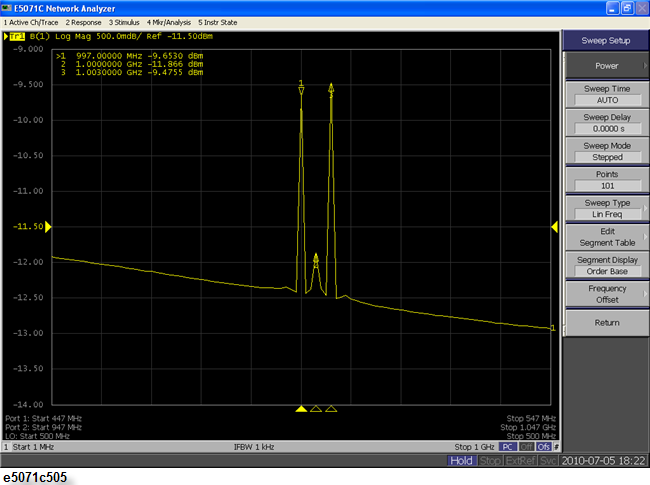
This following figure shows an example of symptom.

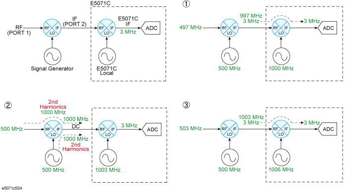
In the configuration at the markers 1 and 3, the measured signal becomes 3 MHz. A signal leakage through the E5071C mixer affects the E5071C IF signal.
In the configuration at the marker 2, the 2nd harmonic of RF and IF is the same as the measured signal. A signal leakage of the 2nd harmonic through the mixier (DUT) affects the measured signal. (This configuration is not a common usage. This is a mathematical example case to explain the symptom.)
|
Marker No. in Example result |
RF |
LO |
Measured Signal (Port 2) |
E5071C_Local |
E5071C_ IF |
|
1 |
497 MHz |
500 MHz |
997 MHz and 3 MHz |
1000 MHz |
3 MHz |
|
2 |
500 MHz |
1000 MHz and DC |
1003 MHz |
||
|
3 |
503 MHz |
1003 MHz and 3MHz |
1006 MHz |
Signal Leakage through mixers
