This section describes the key differences between the Keysight 8753ES and Keysight E5071C.
Other topics about Replacing 8753ES with E5071C
In the 8753ES, channels 1 and 2 are independent from each other and have auxiliary channels, channels 3 and 4, respectively. Channels 3 and 4 can be displayed as additions to channels 1 and 2, respectively. This allows up to four channels to be displayed for up to four traces on the screen simultaneously. Channels 1 and 3 and channels 2 and 4 are always coupled, while channels 1 and 2 are independent from each other. This enables you to specify different sweep conditions on each of channels 1 and 2. The E5071C has 4, 9 , 12, 16 and 36 independent channels, each of which allows sweep conditions to be defined different from those on other channels. On the screen you can open up to maximum 36 windows for channels. The channel allows up to maximum 16 traces to be defined depending on the number of channel.
With the E5071C, you can perform measurements of S parameter and absolute value of the power input into ports. In addition to these, the 8753ES supports measurement parameters such as A, B, R, A/R, B/R, A/B, etc.
The 8753ES comes standard with test sets for two ports, while the E5071C comes optionally with test sets for two ports and four ports. Furthermore, the 8753ES comes optionally with a 75 ohm test set (Option 075), while the E5071C does not.
For more about the measurement frequency ranges of the 8753ES and E5071C, see the following table.
Measurement Frequency Ranges
|
Function |
8753ES |
E5071C |
|
Measurement frequency range |
|
For more about the output power levels and output power ranges of the 8753ES and E5071C, see the following table.
Test Port Output Power Levels
|
Function |
8753ES |
E5071C |
|
Output power levels |
|
|
|
Output power ranges |
|
None |
The list (segment) sweep function enables you to perform measurements corresponding to two or more sweep conditions in one sweep operation and is supported both on the 8753ES and E5071C. While the 8753ES allows only up to 30 segments per table to be defined, the E5071C allows up to 201 segments to be defined. Furthermore, while two or more commands are needed to create a table using GPIB (SCPI) commands on the 8753ES, only one command does the same function on the E5071C.
The 8753ES supports an IF bandwidth up to 6 kHz, but the E5071C supports an IF bandwidth up to 500 kHz, enabling faster sweep operations than with the 8753ES.
While the 8753ES supports automatically selecting the output power range, the E5071C supports only manual selection.
The 8753ES allows you to measure frequency conversion device such as a mixer; since it supports the frequency offset sweep. The E5071C also supports this function when the option 008 is used.
The types of calibration kits supported by the 8753ES and E5071C are shown in the following table.
Supported Calibration Kits
|
Type of calibration kit |
8753ES |
E5071C |
|
7 mm |
|
|
|
3.5 mm |
|
|
|
N type |
|
|
|
2.4 mm |
|
N/A |
|
TRL 3.5 mm |
|
|
|
Others |
User-defined calibration kit |
User-defined calibration kit |
The 8753ES allows only one type of user-defined calibration kit to be saved in the internal memory. Up to 15 classes can be set up when defining calibration kits, including 12 classes (isolation included) to be used for full 2-port calibration and three calibration classes (THRU, reflect, and line/match for TRL*/LRM* calibration. A maximum of seven standards can be defined for each calibration class.
In contrast, the E5071C allows 20 types of user-defined calibration kits to be saved in the internal memory, which include the nine calibration kits registered beforehand. When setting up calibration classes, OPEN, SHORT, and LOAD can be set up on each port and THRU between ports. Eight standards are allowed for each calibration class.
Both the 8753ES and E5071C support ECal measurement. However, each supports slightly different functions. The 8753ES supports enhanced response calibration, 1-port calibration for S11 and S22, and full 2-port calibration. The E5071C provides multi-port calibrations including enhanced response calibration, 1-port calibration for S11 and S22, full 2-port calibration, full 3-port calibration (with 4 ports model) and full 4-port calibration (with option 4 ports model).
The 8753ES allows a frequency array or module information to be read, but these functions are not supported on the E5071C.
The trigger system detects the signal for starting a measurement (trigger) and controls decisions on whether to measure or not measure.
On the 8753ES, the trigger state is available for the pair of a main channel and an auxiliary channel (two pairs: channels 1 and 3 and channels 2 and 4). For each pair, three states are available: Hold, Waiting for Trigger, and Measurement. When a trigger event occurs, one pair of channels in the Waiting for Trigger state are put into a sweep operation. If the other pair is also Waiting for Trigger, then the next trigger event puts it into sweep operation as well. When the sweep condition coupling channels is turned on, the Hold, Waiting for Trigger, and Measurement states are common to all channels. In this case, when a trigger event occurs in the Waiting for Trigger state, all channels are put into sweep operation. For example, when you set channel 1 and 2 to uncouple and sweep each channel, you need to set each channel to Hold state and make trigger events to each channel.
On the E5071C, the trigger system involves states of the entire system and those of each of the channels. Since a trigger event is common to all channels, three system-wide states exist: Hold, Waiting for Trigger, and Measurement. On the other hand, two states exist for each channel: Idle and Startup. For a channel in an Idle state, measurement is not performed at all, while for a channel in Startup state, measurements are started in sequence after an event occurs. When all channels are in an Idle state, the E5071C is in Hold state when viewed as an entire system. If even one Startup state channel exists, the E5071C enters the Waiting for Trigger or Measurement state. Upon a transition from the Waiting for Trigger to the Measurement state, measurement is performed on channels put into Startup state starting with the channel with the smallest channel number.
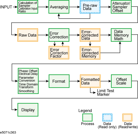
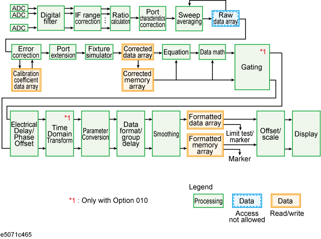
The data flow in the 8753ES is shown in 8753ES Data Flow while the flow in the E5071C is shown in E5071C Data Flow. As described in Reading Writing Data, the types of data you can read/write using the 8753ES differ from those you can read/write using the E5071C.


Types of data that can be handled by the 8753ES and E5071C are listed below.
Reading/Writing Data
|
Function |
8753ES |
E5071C |
|
Data transfer format |
|
|
|
Reading/Writing data |
|
|
|
Reading data |
|
|
The 8753ES allows up to four channels to be displayed on the screen. Up to five markers can be displayed on each channel. Also, one of the displayed markers can be designated as the reference marker. Each channel also supports a fixed marker that can be established at a fixed position.
In contrast, the E5071C enables you to have all 36 channels displayed by opening up 36 separate windows on the screen. Sixteen traces can be displayed for each channel, and up to nine markers can be displayed for each trace. In addition to the markers displayed, you can also designate one marker as the reference marker. The E5071C, however, does not support fixed markers.
The 8753ES supports the Maximum, Minimum, Target value, and Bandwidth marker functions. The E5071C supports all these in addition to a Peak Search function. Using this function, you can determine whether or not to search for a positive or negative peak. In addition, the 8753ES has an additional function to search for the maximum or minimum bandwidth. While the 8753ES allows a target value or search tracking to be established only on the active marker, the E5071C allows a target value or search tracking to be established on all markers.
On the 8753ES, each channel is provided with a memory trace. For this reason, math operations between the data trace and memory trace are supported: Data / Memory and Data - Memory On the E5071C, however, Data * Memory and Data + Memory are supported along with the division and subtraction operations described above.
The trace displays supported on the 8753ES are: "Data trace only", "Memory trace only", "Both memory trace and data trace" and "Data math only". The E5071C supports these functions in addition to "Both data math and memory trace"
The 8753ES supports limit test, ripple test and bandwidth test. The E5071C also supports these tests.
For the limit test on the 8753ES, a limit test table is provided for each channel with up to 18 segments are allowed in each table. In contrast, the E5071C allows a limit test table to be defined for each trace and up to 100 segments to be defined per table.
The 8753ES supports the pass/fail result for each channel, segment or measurement point along with the minimum/maximum measurement value for each segment as retrieved items in test results. On the other hand, the E5071C supports pass/fail results, measurement value, and upper/lower limit values for each measurement point as well as pass/fail results of the active trace for each channel.
Although the 8753ES does not support the fixture simulator function, the E5071C does. The fixture simulator supported by the E5071C include the balanced-unbalanced transformation function for analyzing balanced devices, and the matching circuit function.
For storing data, the 8753ES is provided with an internal register, internal disk drive (floppy disk), and external disk drive (connected through the GPIB). In contrast, the E5071C provides an internal hard disk drive and allows external storage devices such as USB memory. While the 8753ES can save or recall the device setup, screen color settings, and test sequences, the E5071C is able to save or recall the instrument setup, segment sweep table, and limit line table as well as VBA projects. The 8753ES saves display data in JPEG format while the E5071C supports the Windows Bitmap (BMP) and Portable Network Graphics (PNG) format.
Although the 8753ES supports the test sequence program, the E5071C provides an environment for developing VBA programs for automatic measurement.
The 8753ES enables you to establish the print area covering an entire sheet or just a 1/4 sheet, and to define traces, the reference line, and colors of warning messages. In contrast, the E5071C supports only full-sheet output, and an on/off setting for highlighting the entire screen in connection with color setup.
The 8753ES supports parallel ports, serial ports, and GPIB as printer ports, although the E5071C supports only USB-connected printers.
While the 8753ES uses pass control to pass the controller information to an external PC or instrument, the E5071C does not support this function.
Although the 8753ES does not support a LAN interface, support for LANs is standard on the E5071C.
The 8753ES is provided with Take4 mode, mixer measurement function, and harmonics measurement function (Option 002). The E5071C provides the mixer measurement function, and harmonics measurement function with option 008.