Other topics about Frequency Offset Measurement
Using the frequency-offset function and absolute measurement function in combination allows you to measure harmonic distortion of nonlinear devices such as mixers and amplifiers.
|
Item |
Description |
|
Sets the segment table |
|
|
Implements receiver calibration |
|
|
Sets frequency-offset function |
|
|
Sets absolute measurement parameters
|
|
|
Implements harmonic distortion measurement
|
In this case, the segment sweep function is used to perform faster measurement. For detailed information on segment sweep, see Performing a Segment-by-Segment Sweep (segment sweep).
Press Sweep Setup, then click Edit Segment Table to display the Edit Segment Table Menu.
Set Frequency Mode to Center/Span. Refer to the following table to input numbers in the segment table, then click Return to go back to the Sweep Setup Menu.
|
Center |
Span |
Point |
|
500 MHz |
0 Hz |
1 |
|
1 GHz |
1 MHz |
5 |
|
2 GHz |
1 MHz |
5 |
|
3 GHz |
1 MHz |
5 |
|
3.5 GHz |
0 Hz |
1 |
Set Segment Display to Freq Base.
Click Sweep Type to select Segment.
Set the power level using Power.
Set the IF bandwidth.
Receiver calibration is required for the absolute measurement. Receiver calibration of the port to be used for the measurement increases the accuracy in the absolute measurement.
For detailed information on receiver calibration, see Receiver Calibration.
The frequency-offset function allows you to make measurements while the frequencies are different at each test port. In this case, measurement is done by using the setting example for measurement frequency in the following figure. For the setting of frequency-offset sweep, see Setting Frequency-Offset.
The frequency-offset function has an added absolute measurement function.
Follow the steps below to set the absolute measurement parameters.
Press Channel Next/Channel Prev and Trace Next/Trace prev to activate the trace for which you want to implement absolute measurement.
Press Meas to display the Measurement Menu.
Click Absolute to select measurement parameters.
|
Softkey |
Function |
|
A (n) |
Absolute measurement in Port 1, test receiver |
|
B (n) |
Absolute measurement in Port 2, test receiver |
|
R1 (n) |
Absolute measurement in Port 1, reference receiver |
|
R2 (n) |
Absolute measurement in Port 2, reference receiver |
n in the parentheses is the stimulus port number.
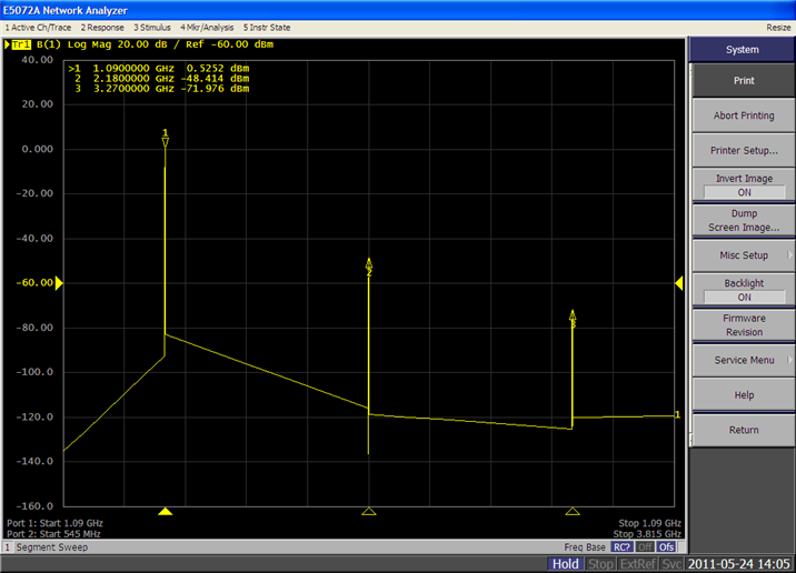
Harmonic distortion is a typical measurement parameter of nonlinear devices such as mixers and amplifiers. As shown in the following figure, the second and third distortions increase by square and cube values of the fundamental signal, respectively. Thus the distortion component increases as a function of the fundamental signal power, and the harmonic distortion can be measured as the proportion of the 2nd and 3rd harmonic power levels to the fundamental signal power level.
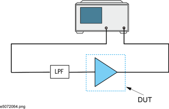
Connect the DUT as shown below. A band pass filter or low pass filter is recommended to place between the DUT and source port in order to reduce the factor of the E5072A harmonics. The pass band of the filter should be include the fundamental frequency.
Follow the steps below to set the measurement parameters. In this case, we measure the harmonic distortion magnitude by using the frequency-offset sweep and the absolute measurement function, based on the E5072A's internal signal source.
Press Channel Next/Channel Prev and Trace Next/Trace Prev to activate the trace for which you want to implement absolute measurement.
Press Meas to display the Measurement Menu.
Click Absolute to select absolute measurement parameters (B (1)). Accordingly, the stimulus port and test port are set to 1 and 2, respectively.
Press Scale to use Auto Scale All for trace scale optimization.
For additional information about the absolute measurements, see Keysight application note 1463-6 Accurate Mixer Measurements Using the Frequency-Offset Mode, 5989-1420EN (Internet Connection is required to open).