How to perform a Cal All Channels Calibration
Using Hardkey/SoftTab/Softkey
-
Press Cal > Other Cals > Cal All....
![]()
"Cal All" allows you to calibrate multiple channels in a single calibration session. This not only reduces the number of connections that need to be made, but also the number of cal standard measurements that must be performed.
Note: Beginning with the A.12.80 release, Cal All has been extended in order to deal with the new Low Frequency Extension option. If a user has a mixture of LFE and non-LFE channels and they would like to use Calibrate All to calibrate them at the same time, two calibration channels are created to account for the hardware differences between the two situations. When using the GUI or COM to set calibration and stimulus conditions, the settings are applied to both calibration channels. With SCPI, the user can query the primary guided calibration channel using SYST:CAL:ALL:GUID:CHAN:VAL?. This will return the primary calibration channel. When subsequent Guided Cal commands are used, settings will be transferred to the second calibration channel. If there is a desire to set these settings separately, the user should query for all Cal All Calibration channels with SYST:CAL:ALL:GUID:CHAN:LIST?. The user should set values for the primary calibration first, and then secondary calibrations. When initializing the calibration and acquiring steps, use the primary cal all channel number.
In this topic:
Cal All offers a single, optimized calibration procedure for all channels (with some limitations, see below). The optimizations include:
Minimizing the number of physical connection of standards.
Minimizing the number of power meter calibration sweeps.
User-settable power levels for S-Parameter as well as power calibration steps.
Accounting for different switch and attenuator settings among different channels. This reduces the number of measurements required to characterize different switch/attenuator settings (channel setup differences).
Cal All will produce the same number and format of Cal Sets (error terms) that would be realized had the calibrations been performed one at a time.
Calibrate External Sources that are connected to the analyzer using Configure an External Source.
Cal All is performed at one IFBW.
All channels that are calibrated are forced into stepped sweep mode.
All channels to be calibrated MUST have the same cal reference plane. In other words, Cal All cannot compensate for any path changes that occur external to the analyzer.
How to perform a Cal All Channels Calibration |
|
Using Hardkey/SoftTab/Softkey |
|
|
|
|
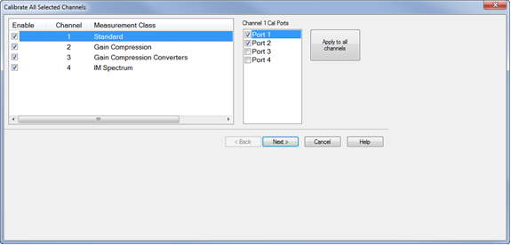
Confirm or change the following unique cal properties for each channel to be calibrated. Click a link to learn about these properties. The properties with (NOT available in Cal All) are NOT available in a Cal All calibration as they are in a stand-alone calibration. SMC
Standard Channel
The power cal is optional only if none of the selected channels require a power cal. |
||||||||||||||||||
|
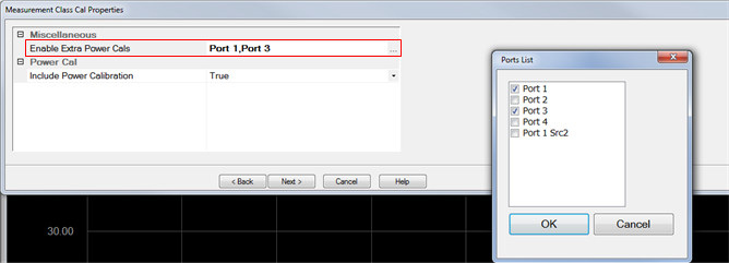
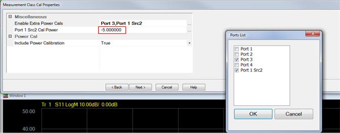
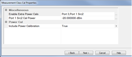
Independent Power Calibration Several applications control internal and external sources in a mode that is often decoupled from the span over which the receivers are swept. This includes, for instance, Differential IQ, and Spectrum Analyzer. Cal All can add a power calibration for any port (including external sources) over an arbitrary frequency span defined by the user. For all ports selected for an independent power calibration (except for Port 1 Src 2, see below), a power sensor calibration measurement is performed. The resulting source match correction terms are added to the calsets for ALL channels selected for the Cal All calibration. The power calibrations used in Cal All have all the same features as typical power calibrations. These include the ability to specify power offsets, the power at which the calibration is completed, and the ability to use multiple power sensors (note that using multiple power sensors is a feature only available on regular PNA ports – that is, not external sources or auxiliary ports). Port 1 Src2 Calibration The Port 1 Src2 calibration is a special case: In this case, a calibration is requested for situations where the Port 1 Bypass Switch is in “Combiner Path” mode and either the “Port 3 Bypass Switch” (4-port PNA-X) or the “Source 2 out 1 Bypass Switch” (2-port 2-source PNA-X) is also in “Combiner Path”. Therefore, if a user requests a calibration of this port:
Important Notes:
Independent Power Calibration for Cal All Setup
|
|
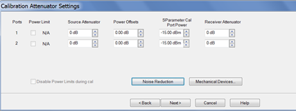
This dialog shows the Power, Attenuator, and IFBW settings for the Cal All calibration. The default values for the Cal All session are the preset values of a standard S-parameter channel. These values are not necessarily the same as those of the channels that are selected for calibration. When there are differences in measurement path (switch) settings between the Cal All channel and the selected channels, these differences are detected by Cal All and additional measurements are made for each path condition. These additional measurements allow Cal All to produce error terms appropriate for each of the selected channels. In general, the Cal All session should be performed at a power level that is high enough to prevent noise in the error terms. However, an increase in power could cause compression or damage to the analyzer receivers. The following settings allow you to increase the power level ONLY during the Cal All session. Power Limit (Disable) Cal All shows you when power limits are enabled. This setting provides you a convenient way to TEMPORARILY disable these limits in order to take advantage of the power settings available in Cal All. If power limits are on, your DUT is probably a high-gain device and the attenuator settings in your channels are high resulting in lower power at the cal reference plane. This lower signal can result in noisier measurements during the acquisition of cal. This situation is precisely what Cal All is intended to improve. Cal All allows you to configure the calibration conditions for better signal-to-noise performance during the cal while leaving your DUT conditions alone. You can elect to clear the “Disable Power Limits during cal” checkbox when you prefer to calibrate at a higher power level than is allowed by your limit. The limit is restored after the Cal All session. Source / Receiver Attenuator By default, the Cal All calibration is performed with Source and Receiver attenuators set to 0. Change the Source or Receiver attenuator settings when external hardware (such as a booster amplifier) would cause the analyzer receivers to be compressed or damaged. You may also want to change the attenuator or path configuration settings to force the cal channel to match settings of the selected channels. If all of the selected channels are set to identical hardware settings, it may be better to apply these settings to the cal channel. For example, if your channels all use a 5 or 10 dB attenuator step at port 1, you might elect to change the Cal All channel to use the same low attenuator settings. This will result in the cal measurements being made under the same path conditions as the channel and it will eliminate the need to mathematically compensate for the difference. However, if large attenuator values are used, the default Cal All settings will likely improve your results. S-Parameter Cal Port Power Set the power level at which the S-Parameter cal is performed. Power Offsets Power Offsets are channel-scoped. Consequently, offsets that you already set are NOT automatically copied to the Cal All session. This setting allows you to also apply a Power Offset during the Cal All session. Learn about Power Offsets. This button accesses the following dialog for settings that help reduce trace noise and the noise floor which can lead to better dynamic range and more accurate measurements. Learn more.
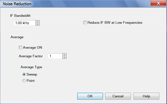
Set the IFBW used to perform the Cal All calibration. The default IFBW setting of 1 kHz is a good nominal setting for most measurements. Lowering the IFBW removes noise from the calibration measurement, but also causes slower sweeps. Always ON Check to enable averaging. Average Factor Specifies the number of measurements that are averaged. Range of 1 to 65536 (2^16). Average Type Sweep Each data point is based on the average of the same data point measured over consecutive sweeps. (Sweep) Restart Begins a new set of measurements that are used for the average. Applies only to Sweep averaging - NOT Point. Point Each data point is measured the number of times specified by the Average Factor, and then averaged, before going to the next data point. Reduce IF BW at Low Frequencies When this box is checked, the VNA uses a smaller IF Bandwidth than the selected value. Learn more. |
For each DUT port:
Check Modify Cal to change the Thru method. An Unknown Thru cal is performed by default. Learn about THRU methods. |
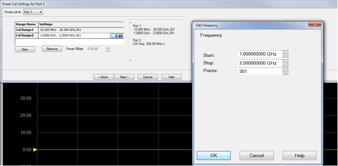
A guided power cal is performed on the source ports for the Cal All calibration. This dialog is displayed for each source port to receive a power cal. To perform an LO power cal for a mixer channel, set the LO port to a VNA or external source in the Mixer Setup dialog. Then select that port in the Selected Channels dialog.
|
|
This page is a summary of the Cal All settings. Confirm the settings, then click Next > or < Back to change settings. |
|
Follow the prompts to connect each standard. Then click Measure. Click Re-measure if necessary. Then click Next >
|
|
Click Finish to save the Cal All session results to Cal Registers. Or click Save As User CalSet, then enter a prefix title. The Meas Class and channel number are appended to this prefix to save to a User Cal Set for each calibrated channel. |