An external SMU Source Measure Unit is a combined DC Source and Meter. The VNA supports the Keysight B2900 series and N6700 series of SMUs. Only the B2900 series offers Hardware Triggering (learn more).
Learn more about the Keysight SMU offerings at: http://Keysight.com/find/smu
For all other External DC devices, select DC Source or Meter Device Type. Learn more about configuring those devices.
How to Configure a SMU
|
|
Using Hardkey/SoftTab/Softkey |
Using a mouse |
|
|
Once configured, set the SMU source voltage and display Voltage / Current Meter measurements:
Note: Gain Compression CSV files contain Voltage / Current settings and measurements |
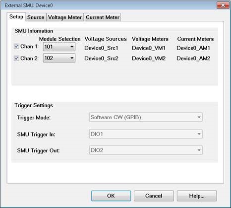
|
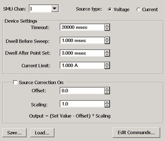
To start this dialog, on the External Device Configuration dialog, select SMU as the Device Type. Then click Device Properties. SMU InformationThe DC device names for six DC devices are listed. The names are made from the root device name (given in the External Device Configuration dialog) plus a suffix. In the above image (example):
Trigger SettingsTrigger Mode: Choose from:
Note: The B2900 series can store no more than 2500 data measurements. Therefore, this mode is NOT allowed when the VNA data points exceed 2500 points. Note: Hardware List trigger mode is NOT supported in GCA 2D sweeps.
|
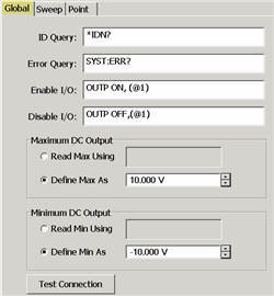
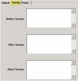
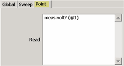
The SMU Source and Meter Edit commands are almost identical in how they operate. Both are documented here. Global TabThe Global tab includes the system settings for the SMU Source. ID Query - Enter the SCPI command to return the ID string of the DC Source. Typically *IDN? This entry can be left blank. Error Query - Enter the SCPI command that is used to return DC Source errors. Typically SYST:ERR? Enable I/O - Enter the SCPI commands that is used to enable the DC Source to output voltages. Disable I/O - Enter the SCPI commands that is used to disable the DC Source from outputting voltages. Maximum / Minimum DC Output (Source ONLY)Read Max / Min Using - Select, then enter the commands used to return the output limits of the SMU source. Define Max / Min As - If the SMU has no commands to return these values, or you would rather define the limit for your SMu, then enter the Max and Min voltage limits. Test ConnectionClick to start the Test Connection dialog. You must first have entered the I/O Configuration settings and select Enable IO on the External Device dialog. Enter a SCPI command, then click Send or Send&Read when a return value is expected. Sweep TabUse the Sweep Tab to send SCPI commands to the SMU at the beginning or end of each sweep. Abort Sweep - Enter the SCPI command that is used to Abort or reset the SMU. This would be necessary when the VNA sweep is aborted or terminated. The VNA will then send the command to the SMU. Point TabRead (commands) - Enter the SCPI command that is used to make a DC measurement at each data point. Set (commands) - Use <%variable> to make a DC Meter setting. |