When you encounter a problem on the M9485A launcher such as the modules cannot be displayed, execute the following steps.
Close the M9485A SFP launcher.
Execute the Connection Expert.
Click "Rescan" button at the top left in the Instrument tab.
Execute the M9485A SFP launcher.
If it is still not resolved, reboot the system (chassis and PC).
If it is still not resolved, reinstall the IO library.
When the operator's check or start up self test is failed, read the dialog message and check the cable connection first. The cable connection includes not only cable itself but also the divider and smp-smp adapter which connects between receiver modules and divider.
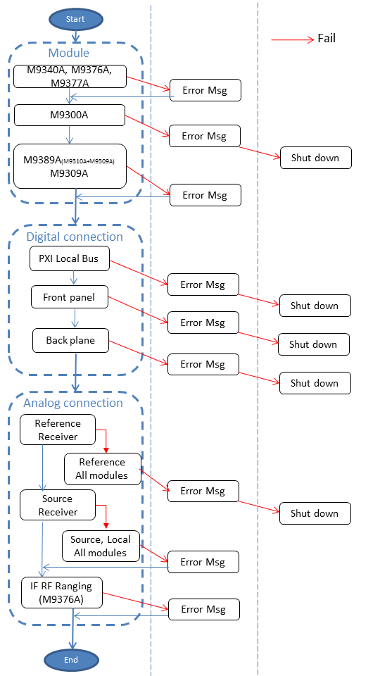
The operator's check consists of the following three parts.
Module Check
Digital Connection Check
Analog Connection Check
The following figure shows the flow. When a test is failed, an error message is displayed and store the failed information into the log file.

When you have this error, replace the module into the other slot. If the failed slot is still the same, the chassis is suspicious.
Check the front panel cable connections.
Check the Connection Expert to confirm if the chassis is detected correctly.
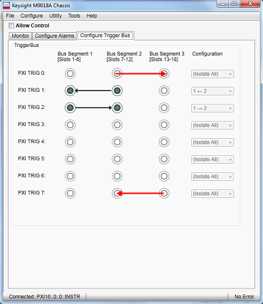
When you are using non-keysight chassis and digital connection test failed, check the trigger bus routing of chassis. See FAQ of M9485A in the Keysight web page for non-Keysight chassis setup. The trigger bus routing for the Keysight chassis is defined automatically, however, check the chassis SFP to confirm if the trigger bus routing is correct. Refer to the Trigger Bus Routing below. If it is not correct, see Trouble_on_Launcher.
If multiple failures occur, open the M9485A_SelftestLog.txt under C:\Users\Public\Public Documents\Network Analyzer. Check the failed test number (Rx, Sx or Lx) in the log file. See the following tables to find out the failure point.
Here are notes for troubleshooting.
When both module and analog connection checks are failed at the same time, refer to the module test first and check it. When both Sxx and Lxx are filed at the same time in analog connection check, refer to Lxx first and check it. If it seems good, refer to Sxx result.
When PXI trigger bus connection test is failed, confirm if the Connection Expert detects the chassis by clicking "Rescan" in its Instrument tab, then restart Soft Front Panel (SFP) again. If it is still failed, the chassis may have problem. If you are using non-Keysight chassis, see FAQ of M9485A in the Keysight web page for non-Keysight chassis setup.
When the self test is passed but the absolute measurement is noisy, confirm if the unused output ports on the M9340A are terminated with 50 Ω loads.
If you have some same modules, swapping the modules will help to isolate the module.
***: Most suspicious, ** : Middle, *: Low
F: Fail, Blank: Pass, NC: Pass or Fail
R6: M9309A Synthesizer Module 100MHz Output Test (Left one, for source signal)
R7: M9310A Source Output Module 100MHz Input Test
|
Test No. |
Suspicious Points |
|||
|
R6 |
R7 |
M9309A (Left one, Source) |
Connection between M9309A (Left one, Source) and M9310A |
M9310A |
|
F |
F |
*** |
|
|
|
|
F |
|
** |
* |
R11: M9376A/M9377A Receiver Module{1-12} 100MHz In 100MHz Input Level Test
R12: M9376A/M9377A Receiver Module{1-12} 100MHz In 100MHz Input Frequency Test
|
Test No. |
Suspicious Points |
||
|
R11 |
R12 |
Connection between M9300A and M9376A/M9377A |
M9376A/M9377A |
|
F |
F |
** |
* |
|
|
F |
*** |
|
S19: M9310A Source Output Module Output Amp Test1
S20: M9310A Source Output Module Output Amp Test2
S4: M9340A Distributor Module A In Source Input Level Test
S5: M9340A Distributor Module A In Source Frequency Test
S6: M9340A Distributor Module A Out1/2/3 Source Output Test
S7: M9376A/M9377A Receiver Module{1-12} Source In Source Input Test
S8: M9376A/M9377A Receiver Module{1-12} Source Connection Test
S9: M9376A Receiver Module{1-12} Test Port Test (No test for M9377A)
|
Test No. |
Suspicious Points |
|||||||||||
|---|---|---|---|---|---|---|---|---|---|---|---|---|
|
S19 |
S20 |
S4 |
S5 |
S6 |
S7 |
S8 |
S9 |
M9310A |
Connection between M9310A and M9340A |
M9340A |
Connection between M9340A and M9376A/M9377A |
M9376A/M9377A |
|
F |
F |
F |
F |
F |
F |
F |
F |
*** |
|
|
|
|
|
|
F |
F |
F |
F |
F |
F |
F |
*** |
|
|
|
|
|
|
|
F |
F |
F |
F |
F |
F |
* |
** |
* |
|
|
|
|
|
|
F |
F |
F |
F |
F |
|
*** |
|
|
|
|
|
|
|
|
F |
F |
F |
F |
|
|
*** |
|
|
|
|
|
|
|
|
F |
F |
NC |
|
|
|
|
*** |
|
|
|
|
|
|
|
F |
NC |
|
|
|
*** |
|
|
|
|
|
|
|
|
|
F |
|
|
|
|
*** |
|
|
|
|
|
|
F |
|
NC |
|
|
|
*** |
|
L1: M9309A Synthesizer Module LO Output Test (Right one, for LO signal)
L2: M9340A Distributor Module B In LO Input Level Test
L3: M9340A Distributor Module B In LO Input Frequency Test
L4: M9340A Distributor Module B Out1/2/3 LO Output Test
L5: M9376A/M9377A Receiver Module{1-12} LO In LO Input Test
L6: M9376A/M9377A Receiver Module{1-12} LO In LO Connection Test
|
Test No. |
Suspicious Points |
|||||||||
|
L1 |
L2 |
L3 |
L4 |
L5 |
L6 |
M9309A (Right one, LO) |
Connection between M9309A (Right one, LO) and M9340A |
M9340A |
Connection between M9340A and M9376A/M9377A |
M9376A/M9377A |
|
F |
F |
F |
F |
F |
F |
*** |
|
|
|
|
|
F |
F |
F |
F |
F |
|
** |
* |
|
|
|
|
|
|
F |
F |
F |
F |
|
*** |
|
|
|
|
|
|
|
F |
F |
F |
|
|
*** |
|
|
|
|
|
|
|
F |
F |
|
|
|
|
*** |
|
|
|
|
|
|
F |
|
|
|
*** |
|
|
|
|
|
|
F |
|
|
|
|
*** |
|
If your configuration includes M9377A, refer to the Port Configuration Wizard or the installation guide.
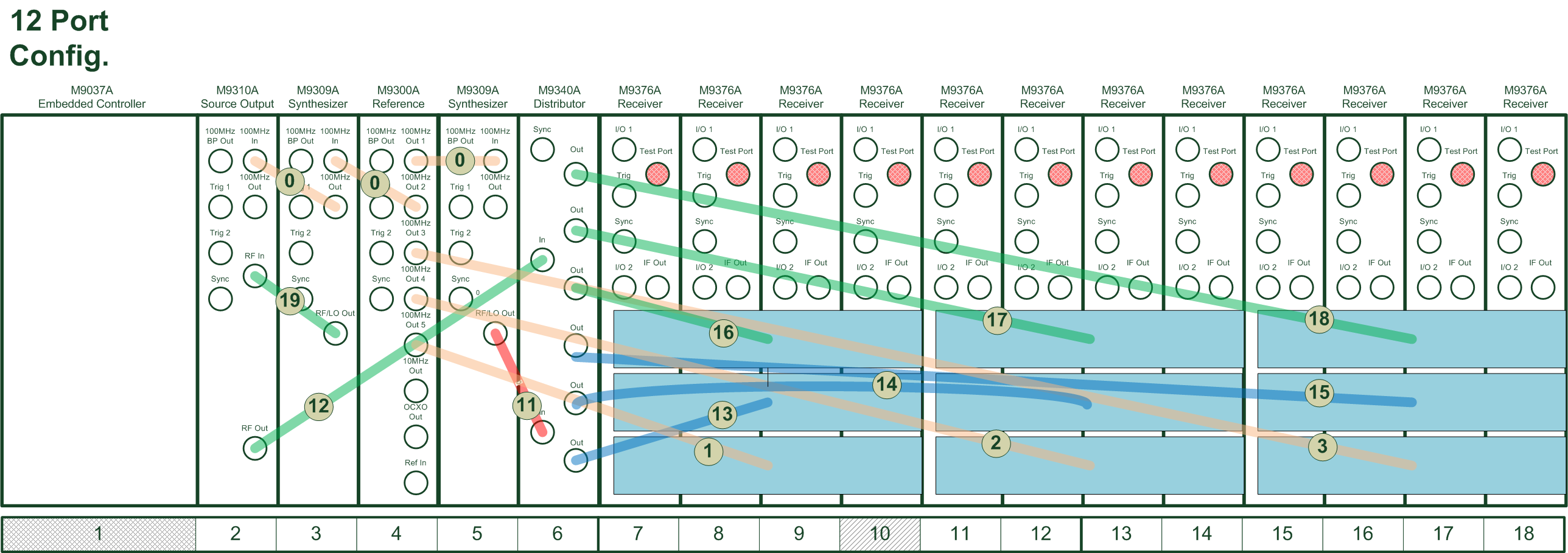
When the number of receivers is equal and more than 7, the red arrows should be connected.
***: Most suspicious, ** : Middle, *: Low
F: Fail, Blank: Pass
Chassis A: has M9310A and M9309A
Chassis B: has M9300A
Note: Refer to PXI/AXIe Chassis tab in Keysight Connection Expert for chassis No. 1 or 2 in the error message.
R6: M9309A Synthesizer Module 100MHz Output Test (Left one, for source signal)
R7: M9310A Source Output Module 100MHz Input Test
|
Test No. |
Suspicious Points |
|||
|
R6 |
R7 |
M9309A (Left one, Source) |
Connection between M9309A (Left one, Source) and M9310A |
M9310A |
|
F |
F |
*** |
|
|
|
|
F |
|
** |
* |
R13: M9340A Distributor Module{1,3} B In 100MHz Input Level Test
R14: M9340A Distributor Module{1,3} B In 100MHz Input Frequency Test
R15: M9340A Distributor Module{1,3} B Out1/2/3 100MHz Output Test
R11: M9376A/M9377A Receiver Module{1-24} 100MHz In 100MHz Input Level Test
R12: M9376A/M9377A Receiver Module{1-24} 100MHz In 100MHz Input Frequency Test
|
Test No. |
Suspicious Points |
|||||||
|
R13 |
R14 |
R15 |
R11 |
R12 |
Connection between M9300A and M9340A (Left one in Chassis A or Chassis B) |
M9340A (Left one in Chassis A or Chassis B) |
Connection between M9340A (Left one in Chassis A or Chassis B) and M9376A/M9377A |
M9376A/M9377A |
|
F |
F |
F |
F |
F |
** |
* |
|
|
|
|
F |
F |
F |
F |
*** |
|
|
|
|
|
|
F |
F |
F |
|
*** |
|
|
|
|
|
|
F |
F |
|
|
** |
* |
|
|
|
|
|
F |
|
|
*** |
|
S19: M9310A Source Output Module Output Amp Test1
S20: M9310A Source Output Module Output Amp Test2
S10: M9340A Distributor Module1 A In Source Input Level Test
S11: M9340A Distributor Module1 A In Source Input Frequency Test
S12: M9340A Distributor Module1 A Out1/2/3 Source Output Test
|
Test No. |
Suspicious Points |
||||||
|---|---|---|---|---|---|---|---|
|
S19 |
S20 |
S10 |
S11 |
S12 |
M9310A |
Connection between M9310A and M9340A (Left one in Chassis A) |
M9340A (Left one in Chassis A) |
|
F |
F |
F |
F |
F |
*** |
|
|
|
|
F |
F |
F |
F |
*** |
|
|
|
|
|
F |
F |
F |
* |
** |
* |
|
|
|
|
F |
F |
|
*** |
|
|
|
|
|
|
F |
|
|
*** |
S4: M9340A Distributor Module{2,4} A In Source Input Level Test
S5: M9340A Distributor Module{2,4} A In Source Frequency Test
S6: M9340A Distributor Module{2,4} A Out1/2/3 Source Output Test
S7: M9376A/M9377A Receiver Module{1-24} Source In Source Input Test
S8: M9376A/M9377A Receiver Module{1-24} Source Connection Test
S9: M9376A Receiver Module{1-24} Test Port Test (No test for M9377A)
|
Test No. |
Suspicious Points |
||||||||
|
S4 |
S5 |
S6 |
S7 |
S8 |
S9 |
Connection between M9340A (Leftt one in Chassis A) and M9340A (Right one in Chassis A and B) |
M9340A (Right one in Chassis A and B) |
Connection between M9340A (Right one in Chassis A and B) and M9376A/M9377A |
M9376A/M9377A |
|
F |
F |
F |
F |
F |
F |
** |
* |
|
|
|
|
F |
F |
F |
F |
F |
*** |
|
|
|
|
|
|
F |
F |
F |
F |
|
*** |
|
|
|
|
|
|
F |
F |
NC |
|
|
|
*** |
|
|
|
|
|
F |
NC |
|
|
*** |
|
|
|
|
|
|
|
F |
|
|
|
*** |
|
|
|
|
F |
|
NC |
|
|
*** |
|
L1: M9309A Synthesizer Module LO Output Test (Right one, for LO signal)
L7: M9340A Distributor Module3 A In LO Input Level Test
L8: M9340A Distributor Module3 A In LO Input Frequency Test
L9: M9340A Distributor Module3 A Out1/2/3 LO Output Test
|
Test No. |
Suspicious Points |
|||||
|
L1 |
L7 |
L8 |
L9 |
M9309A (Right one, LO) |
Connection between M9309A (Right one in Chassis A) and M9340A (Left one in Chassis B) |
M9340A (Left one in Chassis B) |
|
F |
F |
F |
F |
*** |
|
|
|
|
F |
F |
F |
** |
* |
|
|
|
|
F |
F |
*** |
|
|
|
|
|
|
F |
|
*** |
|
L2: M9340A Distributor Module{2, 4} B In LO Input Level Test
L3: M9340A Distributor Module{2, 4} B In LO Input Frequency Test
L4: M9340A Distributor Module{2, 4} B Out1/2/3 LO Output Test
L5: M9376A/M9377A Receiver Module{1-24} LO In LO Input Test
L6: M9376A/M9377A Receiver Module{1-24} LO In LO Connection Test
|
Test No. |
Suspicious Points |
|||||||
|
L2 |
L3 |
L4 |
L5 |
L6 |
Connection between M9340 (Right one in Chassis B) and M9340A (Left one in Chassis B) |
M9340A (Right one in Chassis A and B) |
Connection between M9340A (Right one in Chassis A and B) and M9376A/M9377A |
M9376A/M9377A |
|
F |
F |
F |
F |
F |
** |
* |
|
|
|
|
F |
F |
F |
F |
*** |
|
|
|
|
|
|
F |
F |
F |
|
*** |
|
|
|
|
|
|
F |
F |
|
|
|
*** |
|
|
|
|
|
F |
|
|
*** |
|
|
|
|
|
F |
|
|
|
*** |
|
If your configuration includes M9377A, refer to the Port Configuration Wizard or the installation guide.
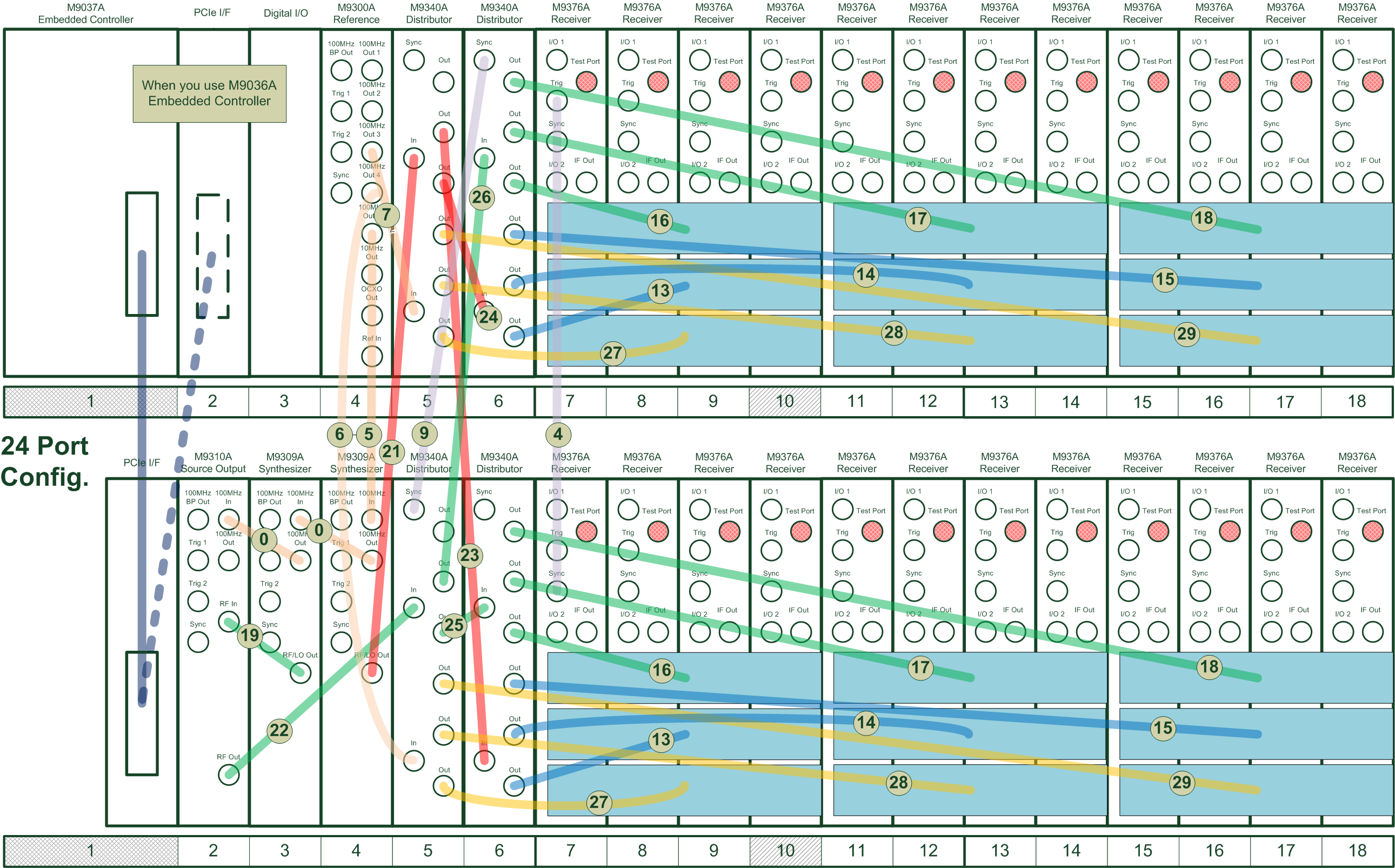
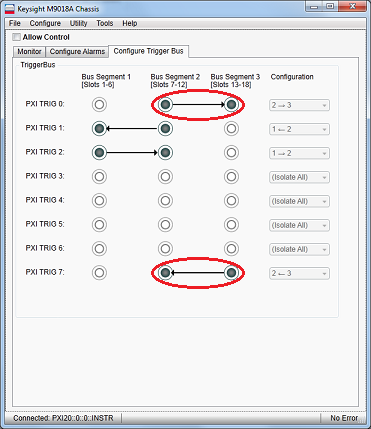
When the number of receivers is equal and more than 6, the arrows in red circle are not connected.
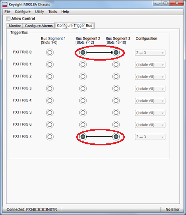
When the number of receivers is equal and more than 6, the arrows in red circle are not connected.
Last modified:
|
18-May-2016 |
New topic |