The Agilent N5182A MXG RF vector signal generator and the Agilent E4438C ESG vector signal generator are the two signal generators that can be controlled by the PXB. The PXB has the following model number and firmware revision requirements for the MXG and the ESG.
Agilent N5182A MXG signal generator with firmware revision A.01.44 or later (See Keys to Success for details)
Agilent E4438C ESG-C signal generator with firmware revision C.05.23 or later (See Keys to Success for details)
Other signal generators may be used with the PXB, however they cannot be controlled through PXB's user interface.
The Signal Generator setup pane is comprised of five buttons and two tabs which are located at the top of the page.
Click a button in the graphic below to link to the button description.
Click a tab in the graphic below to link to the settings descriptions for the tab.
The two tabs are:
General Settings is used to set up the signal generator
Marker Routing is used to set up the marker routing settings for the signal generator.
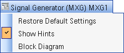
The name of the block (in this case, Signal Generator (MXG) MXG1) is
displayed at the top of the setup pane. This name was assigned when the
signal generator was registered during the signal generator setup and
displayed in the External
Instrument Table and the block diagram. When the  name is selected,
additional choices, including a selection to show or hide the Hints area,
are displayed.
name is selected,
additional choices, including a selection to show or hide the Hints area,
are displayed.
There are also several buttons located immediately below the signal generator name. The following is a description of each button:
|
|
Selecting Reset has no effect on the signal generator values that are displayed. You must select Update From Inst to see the current signal generator values in the PXB user interface. |
Power
Search initiates a power search. This button is only active when
ALC is set to Off.
Test
Connection tests the connection between the PXB and the signal
generator. If the test connection fails, refer to the external instrument
setup dialog box to verify that all LAN/GPIB addresses are valid. Ensure
that all cables are securely connected to the correct input/output connectors
on the respective instruments.