N5110B Capture Setup
Capture Setup
Capture method
This cell determines the type of memory the waveform will be saved to
during capture. Your choice will depend on the waveform size and the desired
playback sample rate.
|
Optimize Depth |
With this choice,
the captured waveform is saved to the hard drive. Optimizing for depth
will provide virtually unlimited depth at the cost of speed. Waveform
file size is limited only by the available space on the hard drive. The
speed is limited to 40 MSa/s, although it is not guaranteed. |
|
Optimize Speed |
With this choice,
the waveform file contents are copied to the DRAM
on board the N5101, and playback occurs from the DRAM. Optimizing for
speed will allow the highest sample rates but limit the maximum depth
of capture. Waveform file size is limited by the available DRAM. |
|
Automatic Selection |
With this choice,
the waveform file will load into and play back from DRAM if the waveform
will fit (<=512 MSamples). Otherwise, playback will occur directly
from the hard drive. |
Capture Depth
This cell sets the number of samples in the capture. This setting is
coupled with the sample rate and capture duration settings. If the capture
depth is set and the rate is changed, the capture depth will remain constant
and the capture duration will be updated based on the new sample rate.
If the capture duration is set and the sample rate is changed, the capture
depth will change to attempt to keep capture duration constant (if this
is not possible, the capture duration will be clipped at the limit).
Capture Duration
This cell sets the duration of the capture, specified in a time unit
(nS, uS, S) Capture
duration is coupled with the sample rate and capture depth settings. If
the capture duration is set and the sample rate is changed, the capture
depth will change to attempt to keep capture duration constant (if this
is not possible, the capture duration will be clipped at the limit). If
the capture depth is set and the rate is changed, the capture depth will
remain constant and the capture duration will be updated based on the
new sample rate.
Signal Setup
Capture Sample Rate
This cell specifies the sample rate of the captured waveform. This cell
controls the N5102A interface module's sample rate setting. It is read-only,
and is determined by the N5102A Digital Interface Clock
Rate, Serial/Parallel,
and Signal
Mapping settings.
Analysis Sample Rate
This cell specifies the sample rate used to analyze the waveform. This
cell controls the Agilent 89601 signal analysis software's sample rate
setting. When Lock Sample Rates is set to True, this
is a read-only value that is equal to the capture sample rate.
Lock Sample Rates
This cell allows the user to lock the Analysis Sample Rate and Waveform
Sample Rate settings.
|
True |
With this choice,
the analysis sample rate will always be the same as the waveform sample
rate. |
|
False |
With this choice,
the capture sample rate and the analysis sample rate are independent settings. |
Trigger Setup
Trigger Type
This cell selects the source of the trigger signal.
|
Free Run |
With this choice,
capture occurs upon clicking the play  button. Capture stops upon reaching the defined
capture depth. button. Capture stops upon reaching the defined
capture depth. |
|
Device Bus |
With this choice,
capture begins upon receiving a trigger signal from a designated pin on
the device breakout board. Capture stops upon reaching the defined capture
depth. |
|
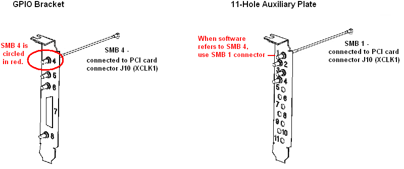
SMB 4 |
With this choice,
capture begins upon receiving a trigger signal through the SMB 4 GPIO
port on the N5101A PCI card. Capture stops upon reaching the defined capture
depth.
(View the SMB 4 connector location with both styles of the PCI Card Bracket)
|
|
Magnitude |
With this choice,
capture begins on the first sample that has a power level greater than
the level set by the Trigger Value parameter. Capture
stops upon reaching the defined capture depth. |
Trigger Value
This cell sets the value to which the Magnitude trigger is compared.
For IQ samples, the trigger value is defined as  . For IF samples, the
absolute value of the sample is the is the trigger value. This setting
is only available when Trigger Type is set
to Magnitude.
. For IF samples, the
absolute value of the sample is the is the trigger value. This setting
is only available when Trigger Type is set
to Magnitude.
Trigger Time Delay
This cell delays or advances the trigger by
+/- (1000 / Sample Rate). The time delay will be rounded to the nearest
1/sample rate.
Trigger time delay is coupled with the sample
rate and the trigger sample delay. If the trigger time delay is set and
the sample rate is changed, the number of samples delayed will change
to keep the trigger time delay constant (if the resulting delay is out
of range, the time delay will be clipped at the limit). If the trigger
sample delay is set and the rate is changed, the sample delay will remain
constant and the time delay will be updated based on the new sample rate.
Trigger Sample Delay
This cell delays
or advances the trigger by +/- 1000 samples. The time delay will be rounded
to the nearest 1/sample rate.
Trigger sample delay is coupled with the sample
rate and the trigger time delay. If the trigger time delay is set and
the sample rate is changed, the number of samples delayed will change
to keep the trigger time delay constant (if the resulting delay is out
of range, the time delay will be clipped at the limit). If the trigger
sample delay is set and the rate is changed, the sample delay will remain
constant and the time delay will be updated based on the new sample rate.
Trigger Time Hold Off
This cell lets you configure the Agilent 89601A analyzer software to
ignore trigger signals for a specified period of time. The next trigger
cannot occur for the length of time specified. See the 89601A documentation
for more information.
Trigger Sample Hold Off
This cell lets you configure the Agilent 89601A analyzer software to
ignore trigger signals for a specified number of samples. The next trigger
cannot occur for the number of samples specified. See
the 89601A documentation for more information.
Trigger Position
This cell determines the location of the trigger point in the waveform
capture window. This cell is disabled (grayed out) if Trigger
Type is set to Free Run.
Related Topics
Basic
Capture Setup
Waveform Setup
N5102A
Digital Interface