Channel Setup – Basic Downlink Carriers
Basic downlink carriers consist of the following:
-
Basic W-CDMA/HSPA DL Rel 7
-
Basic W-CDMA/HSPA+ DL Rel 8
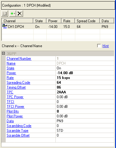
Not all of the parameters shown here are available on all channels. This illustration is a composite of all downlink channel parameters and options, and is not a true representation of a DPCH.
Channel Configuration Summary Table
This table enables you to view the key parameters for each channel in a carrier. You can also add or delete channels using the buttons above the table (see descriptions below). Double-clicking a channel row activates the setup tables for that channel. You can use a maximum of 512 channels per carrier.
 This button opens a window of predefined channel configuration selections
according to the selected carrier type:
This button opens a window of predefined channel configuration selections
according to the selected carrier type:  Basic W-CDMA/HSPA
DL Rel 7
or Basic W-CDMA/HSPA+ DL
Rel 8.
Double-clicking a configuration replaces the current configuration in
the setup table. Select the carrier type from the Waveform or Carrier
views.
Basic W-CDMA/HSPA
DL Rel 7
or Basic W-CDMA/HSPA+ DL
Rel 8.
Double-clicking a configuration replaces the current configuration in
the setup table. Select the carrier type from the Waveform or Carrier
views.
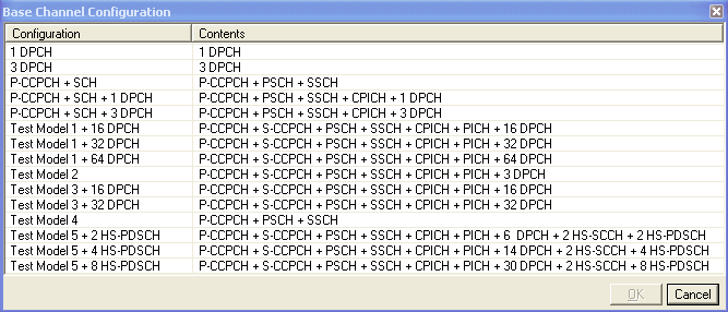
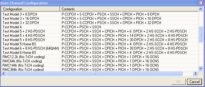
The pre-defined reference measurement channel configurations for Basic W-CDMA/HSPA+ DL Rel 8 are physical channels only and do not include transport channel coding.
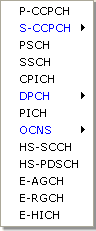
 This button opens a drop-down menu for selecting
a channel to add to the setup table. The channel is inserted above the
currently highlighted channel in the table. Available downlink channels
include:
This button opens a drop-down menu for selecting
a channel to add to the setup table. The channel is inserted above the
currently highlighted channel in the table. Available downlink channels
include:
 This button deletes the currently highlighted
channel(s) in the setup table. You can highlight multiple channels by
holding down the CTRL key while selecting the channels.
You can also use the SHIFT key to select a succession (group) of channels.
This button deletes the currently highlighted
channel(s) in the setup table. You can highlight multiple channels by
holding down the CTRL key while selecting the channels.
You can also use the SHIFT key to select a succession (group) of channels.
 A yellow warning symbol shown with a channel entry
indicates that the parameters of that channel conflict with another channel
of the same carrier. An error message appears in the Status Window and the Status Bar indicating which channels conflict.
A yellow warning symbol shown with a channel entry
indicates that the parameters of that channel conflict with another channel
of the same carrier. An error message appears in the Status Window and the Status Bar indicating which channels conflict.
3GPP
Channel Number
View the channel number of the displayed parameters. The software accepts a maximum of 512 channels. You can change the channel configuration or add individual channels using the buttons at the top of the data summary table.
Name
View the channel type.
State
Double-click or use the drop-down menu to turn the channel on or off.
Power
Range: −60 to 0 dB
Enter the channel power level relative to the carrier power.
Rate
Choices: see Spreading Code for limits
Double-click or use the drop-down menu to set the channel symbol rate.
When grayed out, the rate is fixed for that channel.
For channels that have adjustable symbol rates, you may enter a symbol rate that exceeds the acceptable range, based on the selected spreading code. This condition generates an error, which you correct by selecting a proper spreading code for the symbol rate. The software allows this behavior so that you can set either value first.
Spreading Code
Range: (see table below)
|
DPCH, OCNS |
0–511 @ 7.5 ksps 0–255 @ 15 ksps 0–127 @ 30 ksps 0–63 @ 60 ksps 0–31 @ 120 ksps 0–15 @ 240 ksps 0–7 @ 480 ksps 0–3 @ 960 ksps |
|
S-CCPCH |
0–255 @ 15 ksps 0–127 @ 30 ksps 0–63 @ 60 ksps 0–31 @ 120 ksps 0–15 @ 240 ksps 0–7 @ 480 ksps 0–3 @ 960 ksps |
|
P-CCPCH, CPICH, PICH, E-AGCH |
0–255 @ 15 ksps fixed rate |
|
HS-SCCH, E-RGCH, E-HICH |
0–127 @ 30 ksps fixed rate |
|
HS-PDSCH |
0–15 @ 240 ksps fixed rate |
Enter a value to set the channel spread code number. The spread code is an OVSF code. Ensure that the value entered does not create a code domain conflict with the other physical channels.
You may enter a spreading code value that exceeds the acceptable range, based on the selected symbol rate. This condition generates an error, which you correct by selecting the proper symbol rate for the spreading code. The software allows this behavior so that you can set either value first.
Timing Offset
Range: 0–149
Enter a value to set a timing offset for the selected channel. Each numeric value entered is equivalent to 256 chips or 1/10 of a timeslot offset. The timing offset affects the crest factor of the signal. By varying the timing offset, the probability of channels adding in phase and producing a high peak-to-average ratio or crest factor is minimized. Base stations vary the timing between channels so that amplifiers can operate at the most efficient level.
TPC
Range: 0000–7FFF
Enter the TPC value.
TPC Power
Range: −20 to 20 dB
Set the power level for the channel's TPC bits.
TFCI
Range: 0–1023
Enter a TFCI code. The number of TFCI bits sent to each timeslot is determined by the slot format. The TFCI is an optional field describing what services are in use (for example, data and video). Fixed rate service does not include TFCI.
If this cell is grayed out, you can enable it by turning on TFCI Field at the carrier property pane.
TFCI Power
Range: −20 to 20 dB
Set the power level for the TFCI bits.
Pilot Bits
Choices: (see table below)
|
DPCH |
4 @ 7.5 ksps 2, 4, 8 @ 15 ksps 4, 8 @ 30 ksps 8 @ 60 ksps 8 @ 120 ksps 16 @ 240 ksps 16 @ 480 ksps 16 @ 960 ksps |
|
S-CCPCH |
0, 8 @ 15 ksps 0, 8 @ 30 ksps 0, 8 @ 60 ksps 0, 8 @ 120 ksps 0, 16 @ 240 ksps 0, 16 @ 480 ksps 0, 16 @ 960 ksps |
Set the pilot bits. The number of bits available depends on the slot format of the channel.
Pilot Power
Range: −20 to 20 dB
Set the power level for the pilot bits.
Data
Select a data type using the Data Source Selection dialog box.
For E-HICH and E-RGCH enter a signature sequence index value (0 to 39). This value determines the signature hopping pattern, which is described in TS 25.211.
Without Option FFP, the HS-PDSCH uses only 16QAM modulation.
Scrambling Code
Range: 0–511
Enter a value to set the channel's primary scramble code.
Scramble Type
Double-click or use the drop-down menu to select a scramble type.
-
STD − Uses the standard scrambling code.
-
LEFT − Uses a left alternative scrambling code by adding 8192 to the scrambling code.
-
RIGHT − Uses a right alternative scrambling code by adding 16384 to the scrambling code.
Scramble Offset
Range: 0–15
Enter a scramble code offset value. The offset value is multiplied by 16 and added to the scramble code.
Configuring the Channel Setup View