Waveform Setup
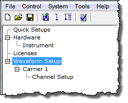
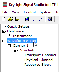
Clicking in the
 tree view
displays the Waveform Attributes settings table in the node view of the
main window.
Carrier Configuration Summary Table
This table enables you to view the key parameters for each carrier in the waveform. You can also add or delete carriers using the buttons above the table (see descriptions below). Double-clicking a carrier row activates the setup tables for that carrier. You can use a maximum of 128 carriers.
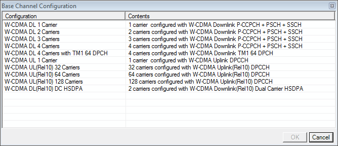
 This button opens a window of
  predefined carrier configuration selections.
Double-clicking a configuration replaces the current configuration in
the setup table.
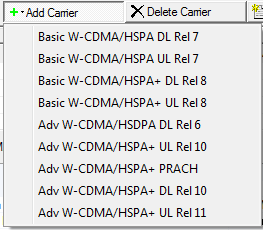
 This button opens a
  drop-down menu
for selecting a carrier to add to the setup table. The carrier is inserted
above the currently highlighted carrier in the table.
 This button deletes the currently highlighted
carriers in the setup table. You can highlight multiple carriers by holding
down the CTRL key while selecting the carriers. You
can also use the SHIFT key to select a succession (group) of carriers.
 This button quickly adds a copy of the selected carrier in the carrier configuration summary table.
 An asterisk shown with a carrier entry indicates that
the parameters of a channel for that carrier have changed.
1. Basic
Waveform Name
Enter an alpha-numeric waveform file name, up to 22 characters in length. The name can include spaces and some special characters: _ $ & # + - [ ]. You can enter a name with more than 22 characters, but when you click outside of the cell, the software truncates the name to 22 characters.
Comment
Enter an alpha-numeric comment up to 32 characters in length. The comment resides in the file header and can include spaces and special characters.
Total Sample Points
View the generated waveform length (number of points). You cannot edit this cell.
I/Q Map
Choices: Normal | Invert
Default: Normal
Double-click or use the drop-down menu to select a normal or inverted I/Q signal.
2. Marker
Marker 1 Source
Choices: None | Frame | 2 ms frame pulse | 10 ms frame pulse | 40 ms frame pulse | RF ALC Control | RF Blanking | Timing Control | User Defined bits
Default: Frame
Configure the marker points for marker 1 using the Marker Source Selection dialog box.
The signal generator outputs the marker 1 signal from the rear-panel EVENT 1 output. For more information, see the signal generator's User Guide.
Marker 2 Source
Choices: None | Frame | 2 ms frame pulse | 10 ms frame pulse | 40 ms frame pulse | RF ALC Control | RF Blanking | Timing Control | User Defined bits
Default: None
Configure the marker points for marker 2 using the Marker Source Selection dialog box.
The signal generator outputs the marker 2 signal from the rear-panel EVENT 2 output. For more information, see the signal generator's User Guide.
Marker 3 Source
Choices: None | Frame | 2 ms frame pulse | 10 ms frame pulse | 40 ms frame pulse | RF ALC Control | RF Blanking | Timing Control | User Defined bits
Default: None
Configure the marker points for marker 3 using the Marker Source Selection dialog box.
The signal generator outputs the marker 3 signal from the rear-panel EVENT 3 output. For more information, see the signal generator's User Guide.
When Parameter Optimization in the Signal Generator node is set to , Marker 3 and Marker 4 source selection in the Waveform Setup node and the marker routing selected in the Dual Arb Marker Utilities are overridden.
To manually set Marker 3 and Marker 4 source, the marker routing, or both, set the Parameter Optimization to .
Marker 4 Source
Choices: None | Frame | 2 ms frame pulse | 10 ms frame pulse | 40 ms frame pulse | RF ALC Control | RF Blanking | Timing Control | User Defined bits
Default: None
Configure the marker points for marker 4 using the Marker Source Selection dialog box.
The signal generator outputs the marker 4 signal from the rear-panel EVENT 4 output. For more information, see the signal generator's User Guide.
When Parameter Optimization in the Signal Generator node is set to , Marker 3 and Marker 4 source selection in the Waveform Setup node and the marker routing selected in the Dual Arb Marker Utilities are overridden.
To manually set Marker 3 and Marker 4 source, the marker routing, or both, set the Parameter Optimization to .


