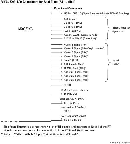
AUX I/O Connector Input Signals
The AUX I/O connector has two nodes that control this port:
-
Instrument—Controls the general operating mode of the AUX I/O that applies to all of the AUX I/O signals.
-
Signal IO—Defines which specific signals are going to be input/output on the AUX I/O port. These are specific to your application and to the type of Signal Studio software used. W-CDMA/HSPA+ has three choices for the Signal IO node:
This topic covers the use case for the AUX input signals and has the following sections (For more information—including AUX external signals—refer to Using the Keysight X-Series Signal Generator AUX I/O Port , AUX I/O Input/Output Pin-outs and Signals  figure and Table 1):
Overview
The AUX input signals are used to provide feedback to the real-time signal generation software, such as N7600C Signal Studio for real-time W-CDMA/HSPA+ signals.
For the N7600C operation, AUX input signaling can be used to provide testing of real-time signal controlling, such as power control loop testing and HARQ testing. An external signal is connected to the AUX input port and used to change signal behavior and to signal a power change for each signal frame for the power control testing, ACK/NACK pattern for HARQ ACK/NACK testing, depends on each feedback signal purpose.
The following feedback signals are available on N7600C:
|
DPCCH/DPDCH Configuration Mode |
|
|
|
|
|
|
|
|
|
PRACH configuration mode |
|
|
|
CELL_FACH |
|
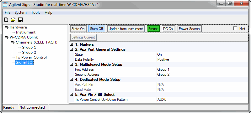
The AUX input port can be configured in the Signal IO node of the N7600C software. Refer to Figures 1, 2, and 3.
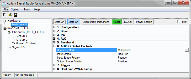
The AUX port has a “Multiplexed” mode and a “Dedicated” mode. Figure 4 indicates that the AUX I/O port is set to “Multiplexed” mode. In Figure 1, notice the parameter area, where the AUX0 pin is selected. This means that the W-CDMA/HSPA+ real-time system will expect you to supply a power control feedback signal using the AUX 0 of the AUX I/O connector.
For the PRACH Signal IO node AUX 0 and AUX 1 are expected to be used for triggering (Figure 2).
For the CELL_FACH Signal IO node AUX 0 is expected to be used for triggering (Figure 3).
Figure 1. Signal IO Node (DPCCH/DPDCH)

Figure 2. Signal IO Node (PRACH)
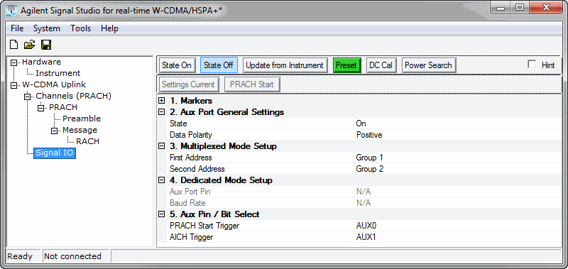
Figure 3. Signal IO Node (CELL_FACH)
Signal IO Node AUX Input Parameters
This section describes the Signal IO node, as it relates to the AUX I/O port input signals. The following AUX port settings are displayed in Figures 1, 2, and 3. For more information, refer to Signal IO DPCCH/DPDCH), Signal IO (PRACH), and Signal IO (CELL_FACH).
AUX Port Generation Settings:
|
State |
On or Off — Off means the AUX signaling is ignored |
|
Data Polarity |
Positive or Negative — Positive means a 3.3-volt signal is interpreted as a ‘1’ and a 0-volt signal is a ‘0’. Negative selection inverts this so that a 3.3-volt signal is interpreted as ‘0’ and 0-volt signal is interpreted as ‘1’. |
|
In the Instrument node, the > can be selected as “Multiplexed” or “Dedicated” – in this case it is selected as “Multiplexed”. Refer to Figure 3 or to the MXG/EXG's User Guide (p/n: N5180-90056). |
|
|
First Address |
For the MXG/EXG it is not necessary to select any Group addresses, so these can be left in their default state. |
|
Second Address |
For the MXG/EXG it is not necessary to select any Group addresses, so these can be left in their default state. |
|
|
|
Aux Port Pin |
Because the AUX port mode is selected as “Multiplexed” these settings are not active, and are shown in grey text. When “Dedicated” mode is selected, this field is used to select the AUX pin of the dedicated connection. |
|
Baud Rate |
Because the AUX port mode is selected as “Multiplexed” these settings are not active, and are shown in grey text. When “Dedicated” mode is selected, this field is used to select the baud rate of the dedicated connection. |
|
|
|
Transmit (Tx) Power Control Up/Down Pattern |
This enables you to select which AUX pin (AUX0 ... AUX11) will be routed to control the N7600C up/down power control function. |
|
Compressed Mode Start Trigger |
Sets the AUX pin of the multiplexed mode for the compressed mode start trigger. |
|
Compressed Mode Stop Trigger |
Sets the AUX pin of the multiplexed mode for the compressed mode stop trigger. |
|
DPCCH TPC User File Trigger |
Sets the AUX pin of the multiplexed mode for the DPCCH TPC user file trigger. |
|
HSUPA HARQ ACK/NACK Pattern |
Sets the AUX pin of the multiplexed mode for the DPCCH TPC user file trigger. |
|
HSUPA TFC E-TFCI Pattern |
Sets the AUX pin of the multiplexed mode for the HSUPA TFC E-TFCI pattern. |
|
|
|
PRACH Start Trigger |
Sets the AUX pin of the multiplexed mode for the PRACH start trigger. |
|
AICH Trigger |
Sets the AUX pin of the multiplexed mode for the AICH trigger. |
|
|
|
Tx Power Control Up/Down Pattern |
Sets the AUX pin of the multiplexed mode for the CELL_FACH pattern. |
Switching AUX input Port Modes
The AUX port has a “Multiplexed” mode and a “Dedicated” mode. In “Multiplexed” mode, auxiliary signaling is sent using level-sensitive binary signaling (3.3V LV TTL) connected to one or more AUX port input bits. In “Dedicated” mode, auxiliary signaling is sent using an RS232C like serial signal at a specified baud rate to a selected AUX port input bit.
The AUX port mode can be selected in the Instrument node's > parameter (see Figure 4), by sending a SCPI command, or by using the instrument's front panel. Refer to the MXG/EXG's User Guide (p/n: N5180-90056).
AUX Port Global Controls
In the Instrument node there are four AUX Port Global controls.
|
Operating Mode |
Select “Multiplexed” or “Dedicated". These functions as described Signal IO Node AUX Input Parameters. |
|
Input Strobe |
There are two selections: Free Run or User. In Free Run mode, the instrument samples the values of the AUX input signals (AUX0 ... AUX11), according to the instruments internal timing – this happens at about 3.5 MHz. In User mode, you must supply a strobe (triggering) signal which causes the AUX input signals to be sampled. |
|
Input Strobe Polarity |
You can choose Positive or Negative polarity. With positive polarity, the AUX input signals are sampled via the rising edge (0V to 3.3V transition) of a pulse (AUX strobe) supplied by you to the AUX I/O connector pin 6. With a negative polarity the AUX input signals are sampled on the falling edge of AUX strobe. |
|
Output Strobe Polarity |
Determines when the AUX input signals have been sampled by looking at the AUX sample clock (connector pin 29) signal. If the Output Strobe Polarity is positive, this will be a positive going pulse (about 200 ns pulse width), which is triggered when the AUX input signals are sampled. If the polarity is negative, the AUX sample clock will be a series of negative going pulses about 200 ns pulse width. |
Operational Signaling Modes
AUX I/O Port: Input Signaling
The Auxiliary I/O port is designed to support your real-time signal generation software configuration with the instrument, and to interface with different configurations of external equipment under test.
For example, consider a sample configuration where you are using W-CDMA/HSPA+uplink signal generation software to control the instrument. The N7600C software can be configured to accept a power up or power down command from external equipment to enable testing of power control loops in base stations.
Auxiliary signaling can be delivered from external equipment in one of two formats.
-
A low-voltage, TTL format where your equipment uses a binary signal connected to the AUX port in an LV TTL format with 0-volts representing a ‘0’, 3.3-volts representing a ‘1'.
If this signal cannot be delivered directly from the external equipment, an inexpensive interface board can be used to connect to external equipment with a USB connection, for example the USB Bit Whacker (SKU: DEV-00762, www.sparkfun.com), can be used to interface from your external equipment with a USB connection to the Keysight Auxiliary I/O port.
-
A serial format where your equipment uses a serial-port connection, with an LV TTL RS-232 type protocol. Baud rates from 9600 to 460800 are supported in this format. For this purpose, a device can use any low voltage transistor to transistor logic (LV TTL) line that can generate RS-232 type signals, or some simple USB to RS-232 TTL signaling devices can be used. See Figure 4.
The default serial format Positive is illustrated in Figures 4 and 5. Each signaling transmission consists of an 8-bit character (bits b7 b6 b5 b4 b3 b2 b1 b0, b0 is least-significant bit, b7 is most significant bit). The signaling transmission consists of a start bit ‘0’, followed by the 8 data bits (transmitted LSB first) followed by a stop bit ‘1’. The bit rate can be one of 9600, 19200, 38400, 57600, 115200, 230400, or 460800 bits per second.
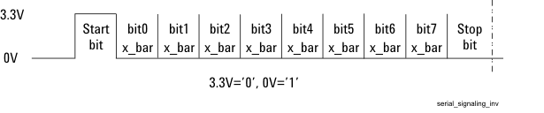
If the polarity is selected as Negative (inverted), then the expected signal will be the inverted form shown in Figure 6.
Figure 4. Serial Data Transmission Format–Polarity is Positive (Default)
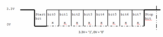
Figure 5. Polarity is Positive - Hex Example
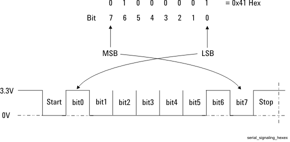
Figure 6. Serial Data Transmission Format–Polarity is Inverted
AUX I/O Port: External Device Signaling (Example)
Again, using the W-CDMA/HSPA+ example in AUX I/O Port: Input Signaling. In this example, your external equipment must communicate a command to control the instrument's W-CDMA/HSPA+ reverse link transmission power for the next frame. The external device transmits a signal to either increase or decrease power. This occurs on each frame. See Figure 7.
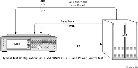
The diagram below shows a typical interconnect diagram with a W-CDMA/HSPA+ base station for purposes of doing base station receiver test. In this example, the instrument RF signal is connected to the input of the base station, an even-second trigger signal is sent from the base station to the instrument PAT TRIG input (BNC connector on the rear panel) enabling the instrument to synchronize it’s frame timing with the base station, and a power control feedback signal connected to the AUX port of the instrument. Refer to Power Control.
Figure 7. W-CDMA Base Station Receiver Testing Connections
In this case, a single binary signal could be used, where a ‘1’ means to increase power and a ‘0’ means to decrease power. The external equipment generates an LV TTL signal for each frame. For this configuration, your equipment connection to the instrument can be as simple as a cable with a single signal wire and a ground connection. For example: connecting the LV TTL signal to pin 8 of the AUX port connector, and ground to pin 20.
The single line's signaling format can be selected as Multiplexed or Dedicated. The instrument's interface enables selection of the signaling format by pressing the following keys:
> > > > > or
-
In the case of mode, the external equipment can send a 3.3-volt signal or 0-volt signal with each frame to communicate a command to increase or decrease power in the next frame.
-
In the case of mode, the external equipment can send a single character each frame to indicate a command to increase or decrease power in the next frame. Any one of these 8-bits, can be used to control the power level in the next frame. In Dedicated mode, your external equipment sends one serial character for each frame.
The instrument's AUX pins, AUX0 to AUX11, are available for delivering auxiliary commands from 1- to 12-bits in width in Multiplexed mode.
In Dedicated mode, where serial format signaling is used, serial signaling can be connected to any one of the pins AUX0 to AUX11.
Dedicated Mode
In Dedicated mode, all signaling is delivered in the serial format as described in AUX I/O Port:Input Signaling. Serial command signals can be connected to the AUX0 to AUX11 pins of the AUX I/O connector. The serial format transmits 8-bits at a time to the instrument. These bits can be mapped to the auxiliary signaling functions of Signal Studio's real-time signal generation software.
The bit assignment on the dedicated mode is fixed for N7600C. The next list shows the bit assignment to the feedback signals on the dedicated mode. The bit assignments are changed by the setting of the channel configuration mode, DPCCH/DPDCH, PRACH, or CELL_FACH mode.
|
DPCCH/DPDCH Configuration Mode |
|
|
BIT0 |
|
BIT1 |
|
BIT2 |
|
BIT3 |
|
BIT4 |
|
BIT5 |
|
|
|
|
PRACH configuration mode |
|
|
BIT0 |
|
BIT1 |
|
CELL_FACH |
|
|
BIT0 |
Multiplexed Mode
In Multiplexed mode, auxiliary commands are delivered as 1- to 12-bit wide commands in LV TTL format.
The same feedback signals supported on the dedicated mode are also available on the multiplexed mode.
Keysight X-Series Signal Generator's User Guide (p/n: n5180-90056)