
|
1. Basic |
2. Marker |
3. Power |
|---|---|---|
|
|
|
|
|
|
|
|
|
|
|
|
|
|
|
|
|
|
|
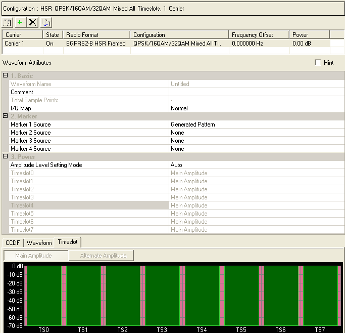
This table enables you to enter a comment, set the I/Q map, and set markers for waveform WFMn, where n is an identifying number for the waveform. You can also add or delete carriers using the buttons above the table (see descriptions below). To activate the setup tables for a carrier, double-click that carrier row.
Click  to open a window with a list of
  pre-defined carrier configurations.
To replace the current configuration in the setup table with one of these
pre-defined configurations, select the desired configuration and click
or double-click the desired
configuration.
Click  to open a
  drop-down
list
from which you can select a carrier to add to the setup table. The carrier
is inserted above the currently selected carrier in the table.
For continuous PN9 data, do not use a high symbol rate (EGPRS2-B) carrier with a normal symbol rate carrier. If you mix the two types of carriers, it will increase the oversampling ratio, which increases the waveform file size.
Click  to delete the currently selected carrier(s) in the
setup table. To select multiple carriers, hold down the key while you click the
desired carriers or use the mouse and the
key to select a group of carriers.
Click  to copy the selected carrier and add the copy to the list of carriers.
The waveform name is automatically generated from the name defined in the Waveform Setup node and is not editable here.
Enter an alpha-numeric comment of up to 32 characters. You can enter a separate comment for each waveform.
"Symbol bit output" is automatically displayed when the symbol bit output mode (Logic Analyzer only) is set to On in the Waveform Setup .
View the number of sample points in the generated waveform. This setting is not editable.
Double-click or use the drop-down menu to select a normal or inverted I/Q signal.
Click  in this cell to open the Marker Source Selection dialog box and configure
the marker points for marker 1.
The signal generator routes the marker 1 signal to the rear-panel EVENT 1 connector 1, marker 2 signal to the rear-panel Event 2 connector output, etc. For more information, see the signal generator's User Guide.
Marker 3 and Marker 4 settings are overridden if Parameter Optimization is enabled.
Event n connector labeling can vary on the different Keysight Signal Generators. Refer to the User's Guide.
Choices: Auto | Manual
Default: Auto
Double-click or use the drop-down menu to set the Amplitude Level Setting Mode.
Choice: Main Amplitude | Alternate Amplitude | None
Default: Main Amplitude
Double-click or use the drop-down menu to set the Timeslot0 to Timeslot7 Marker Power Type.