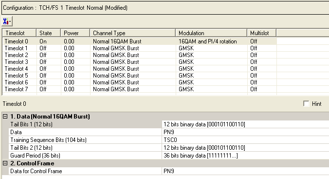
The Normal 16QAM Burst - Advanced is a coded channel that is available with Option QFP. To open the Data node, click Data in the tree view. The figure below shows the Data node. The cells displayed in the Data node are determined by the Channel Type, as defined in the Timeslot window, for the selected timeslot.
The timeslots shown below are set to show all of the available timeslot types, not to show a typical test configuration.

|
1. Data (Normal 16QAM Burst) |
|---|
|
2. Control Frame |
Click  to display a drop-down menu in which you can copy a timeslot configuration
from one timeslot to another.
Use the Data window to define the bits in the bursts. The cells displayed in the Data section are determined by the burst type (Timeslot Type) for the selected timeslot as defined in the Timeslots window. In the window shown above, Timeslot 0 is selected, so the data cells provided are for setting up a Normal 16QAM Burst.

Default: X"166"
Click the Details button  in this cell to open the Data Source Selection window. Enter 12 bits to
use in the first of the two tail bit segments of the normal 16QAM burst.
See
  drop-down figure.
Choice: PN9 |PN15 | User Defined Bits
Default: PN9
Click the Details button  in this cell to open the “Data source selection”
window.
Please select PN9, PN15 or User Defined Bits for encrypted bits.
Select User Defined Bits, to create a custom data string. (See User Defined Bits description)
Choice: TSC0 to TSC7 | User Defined Bits
Default: TSC0
Select to or to use for the training sequence bits.
Click the Details button  in this cell to open the
  Data Source Selection
window.
If you have selected from the  Add New Carrier
drop-down menu, the default training sequence corresponds to the timeslot
number. For example, the default for timeslot 0 is ,
the default for timeslot 1 is,
and so on.
If you manually change a timeslot to a , the training sequence for that timeslot is automatically set to .
The training sequences are defined as follows:
|
TSC0 |
FF 3FF3 F333 FFFF 3FFF 3FF3 F333 |
|
TSC1 |
FF 3F33 F333 F333 3FFF 3F33 F333 |
|
TSC2 |
F3 FFFF 333F 333F 3FF3 FFFF 333F |
|
TSC3 |
F3 FFF3 333F 33F3 FFF3 FFF3 333F |
|
TSC4 |
FF F33F 3F33 3FF3 FFFF F33F 3F33 |
|
TSC5 |
F3 FF33 3F3F 33FF FFF3 FF33 3F3F |
|
TSC6 |
3F 3FF3 3333 F33F FF3F 3FF3 3333 |
|
TSC7 |
33 3F33 33FF F3FF 3F33 3F33 33FF |
Select
User Defined Bits to define custom training sequence bits. See the  drop-down figure.
Default: X"166"
Click the Details button  in this cell to open the
  Data Source Selection
window. Enter 12 bits to use in the second of the two tail bit segments
of the normal 16QAM burst.
Default: X"FFFFFFFFF"
Click the Details button  in this cell to open the
  Data Source Selection
window.
When the Timeslot Timing Mode is set to , the Guard Period is defined as follows:
If the Normal 16QAM Burst is in timeslot 0 or 4, the guard period has 36 bits with a default value of X"FFFFFFFF".
If the Normal 16QAM Burst is in timeslot 1, 2, 3, 5, 6 or 7, the guard period has 32 bits with a default value of X"FFFFFFFFF".
When the Timeslot Timing Mode is set to , the Guard Period is defined as follows:
The guard period in all timeslots has 33 bits (36-bit entry) with a default value of X”FFFFFFFFF”.
Choice: PN9 |PN15 | User Defined Bits
Default: PN9
Set the data for the control frame within a multiframe
setup. Click the Details button  in this cell to open the
  Data Source Selection
window.
Select ,
or . Select , to  create
a data string.
If the Multiframe type parameter at the Carrier n node is set to , the parameter, while appearing as active, has no effect since there is no control frame.