Advanced Carrier Setup (Framed Signal): 1 2 3
|
1. GSM/EDGE |
|---|
|
Multiframe Type |
|
Timeslot Timing Mode |
Choice: On | Off
Default: On
Double-click or use the drop-down menu to set the operating state of the carrier to or .
The selections in this cell are the same as the Timeslot
node's Pre-defined Timeslot Configuration button  .
.
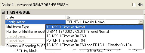
Default: TCH/FS 1 Timeslot Normal
Select a timeslot configuration
from the  drop-down menu.
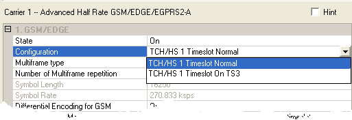
Default: TCH/HS 1 Timeslot Normal
Select a timeslot configuration
from the drop-down menu.
There is only one configuration:
|
UBS-6 1 Timeslot HB |
sets timeslot 0 to a coded UBS-6 and timeslots 1-7 as high symbol rate QPSK bursts |
Default: TCH/FS 1 Timeslot Normal
Select a timeslot configuration
from the drop-down menu.
Choices: 1 | 51 multiframe | 51 multiframe with dummy burst
Default: 51 multiframe
|
1 |
generates a flexible number of frames when used with the multiframe repetitions |
|
51 multiframe |
selects a standard multiframe structure for BCH. |
|
51 multiframe with dummy burst |
sets idle burst to dummy burst in order to achieve a flat power envelope signal. |
The number of multiframes in a multi-carrier waveform is determined by the carrier with the largest number of multiframes (longest waveform length). The current carrier is BCH control channel and there are three multiframe types. In carriers in the waveform with fewer frames, the frames are repeated until the number of multiframes matches that in the longest carrier. For example, for two carriers A and B in the same waveform, if A has 10 frames and B has 3 frames, B is repeated 3 times completely, then one more frame from B is used before both A and B start again.
The maximum waveform length depends on the oversampling ratio, the number of frames, the number of multiframes and repetitions, the number of carriers, and your PC resources (memory size). If an Out of Memory error is reported, reduce the number of frames/multiframes frames, the number of multiframe repetitions, the number of carriers, or the maximum Frequency Offset (reducing the Frequency offset, reduces the oversampling ratio which reduces the amount of PC memory required).
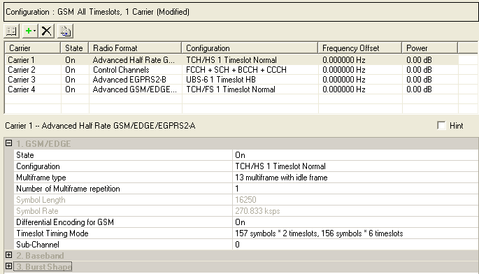
Choice: 13 multiframe with idle frame | 13 multiframe with control frame | 26 multiframe | 52 multiframe
Default: 13 multiframe with idle frame
Double click the cell or use the drop-down menu to make the selection. Select any of the choices to use a continuous PN9 sequence. However to start and end on the boundaries of the PN9 sequence, select either the 13 or 26 multiframe setup. (For more information, see Number of Multiframe Repetition (Advanced GSM/EDGE/EGPRS2-A, EGPRS2-B, and Half Rate GSM/EDGE/EGPRS2-A.))
The waveform length in a multi-carrier waveform is determined by the multiframe (advanced) carrier with the most frames (longest waveform length). The number of frames in a multiframe carrier is a product of the multiframe type and the number of multiframe repetitions. When some of the carriers in the waveform have fewer frames, the frames in the shorter carriers are repeated until their number matches that number in the longest carrier. For example, for two carriers A and B in the same waveform, if A has a 13 multiframe setup with 10 repetitions and B has a 52 multiframe setup with 1 repetition, B will repeat one time, then 26 frames from the B carrier is used before both A and B start again. The same process applies when a non-multiframe carrier is used with a multiframe carrier.
The maximum waveform length depends on the oversampling ratio, the number of frames, the number of multiframes and repetitions, the number of carriers, and your PC resources (memory size). If an Out of Memory error is reported, reduce the number of frames/multiframes frames, the number of multiframe repetitions, the number of carriers, or the maximum Frequency Offset (reducing the Frequency offset, reduces the oversampling ratio which reduces the amount of PC memory required).
Range: 1 to 511
Default: 1
Enter the number of times that the multiframe setup is to repeat.
To seamlessly transmit a PN9 sequence, you need to use 511 repetitions in conjunction with a 13 or 26 multiframe configuration. While 511 repetitions will cause multiple repetitions of the PN9 sequence, the data in the last transmitted frame of the 511 repetitions corresponds to the last data bits of the PN9 sequence. If you use less than 511 repetitions, the PN9 data in the last frame will appear as a truncated PN9 sequence. In addition to selecting the proper multiframe configuration and repetitions for a seamless PN9 transmission, you must also set the oversampling ratio.
The waveform length in a multi-carrier waveform is determined by the multiframe (advanced) carrier with the most frames (longest waveform length). The number of frames in a multiframe carrier is a product of the multiframe type and the number of multiframe repetitions. When some of the carriers in the waveform have fewer frames, the frames in the shorter carriers are repeated until their number matches that number in the longest carrier. For example, for two carriers A and B in the same waveform, if A has a 13 multiframe setup with 10 repetitions and B has a 52 multiframe setup with 1 repetition, B will repeat one time, then 26 frames from the B carrier is used before both A and B start again. The same process applies when a non-multiframe carrier is used with a multiframe carrier.
The maximum waveform length depends on the oversampling ratio, the number of frames, the number of multiframes and repetitions, the number of carriers, and your PC resources (memory size). If an Out of Memory error is reported, reduce the number of frames/multiframes frames, the number of multiframe repetitions, the number of carriers, or the maximum Frequency Offset (reducing the Frequency offset, reduces the oversampling ratio which reduces the amount of PC memory required).
The software sets the symbol length based on the number of frames and the modulation type. This cell is not editable.
This is a fixed value, shown for reference. This cell is not editable.
Choice: On | Off
Default: On
Double-click or use the drop-down menu to set differential data encoding On or Off. This setting is available only for GSM.
Choice: 157 symbols x 2 timeslots + 156 symbols x 6 timeslots | 156.25 symbols x 8 timeslots
Default: 157 symbols x 2 timeslots + 156 symbols x 6 timeslots
Double-click or use the drop-down menu to set the timeslot timing mode. In the default timing mode, timeslots 0 and 4 contain 157 symbols and the remaining timeslots contain 156 symbols.
This function is provided to allow you to switch between a perfectly spaced signal (156.25 symbols * 8 timeslots) and one that is compatible with earlier versions of the signal generation software.
Choice: 188.4 symbols x 2 timeslots + 187.2 symbols x 6 timeslots | 187.5 symbols x 8 timeslots
Default: 188.4 symbols x 2 timeslots + 187.2 symbols x 6 timeslots
Double-click or use the drop-down menu to set the timeslot timing mode. In the default timing mode, timeslots 0 and 4 contain 188.4 symbols and the remaining timeslots contain 187.2 symbols.
Choice: Payload for Each Timeslot Separately | Payload For All Timeslots(On)
Default: Payload for One Timeslot
Double-click or use the drop-down menu to select the PDTCH Payload Mapping Mode.
|
Payload for Each Timeslot Separately |
Each timeslot has its own data source selected in the Data node. |
|
Payload for All Timeslots(On) |
Activates the Payload Data for all Timeslots parameter to select the data to be used for all timeslots. |
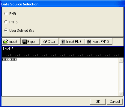
Choice: PN9 | PN15 | User Defined Bits
Default: PN 9
Double-click or use the drop-down menu to set the PDTCH Payload Mapping Mode. This parameter is visible only when the Payload Mapping Mode is Payload For All Timeslots(On).
Click the Details button  in this cell to open the Data Source Selection
window.
in this cell to open the Data Source Selection
window.
Select , , , or to use for the encrypted bits.
Choice: 0 | 1
Default: 0
Double-click or use the drop-down menu to set the sub-channel type.
This Parameter is only available for half rate (HR) GSM carriers.
2. Baseband (Framed Signal - Advanced)