Real Time
Data (Coded UBS-6, UBS-8, and UBS-11 - Advanced)
UBS-6, UBS-8, and UBS-11 are coded channels that are available with
Option QFP. Each of the channel types use a different modulation scheme:
-
UBS-6—QPSK
with 3PI / 4 rotation
-
UBS-8—16QAM
with PI / 4 rotation
-
UBS-11—32QAM
with PI / 4 rotation
To open the Data node, click Data in the .
Use the Data window to define the bits in the bursts. The cells displayed
in the Data node are determined by the Channel Type, as defined in the
Timeslot window,
for the selected timeslot.
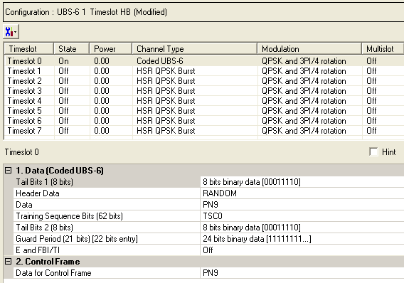
The timeslots shown below are set to show some of the available timeslot
(channel) types, not to show a typical test configuration.
Figure: Coded UBS-6, UBS-8, and UBS-11 Data
Node

Change Data Values Button
Click  to display a drop-down menu in which you can
from one timeslot to another.
Data Node Parameters
Use the Data window to define the bits in the bursts. The cells displayed
in the Data section are determined by the burst type (Timeslot Type) for
the selected timeslot as defined in the Timeslots window. In the window shown above, Timeslot
0 is set up for a data cell with an Uplink level B modulation coding Scheme
6 (UBS-6) burst.
1. Data (HSR QPSK/16QAM/32QAM Burst)
Tail Bits 1 (nn
bits)
Default (UBS-6): X"1E"
Default (UBS-8): X"166D"
Default (UBS-11): X"F79CE"
Click the Details Button  in this cell to open the
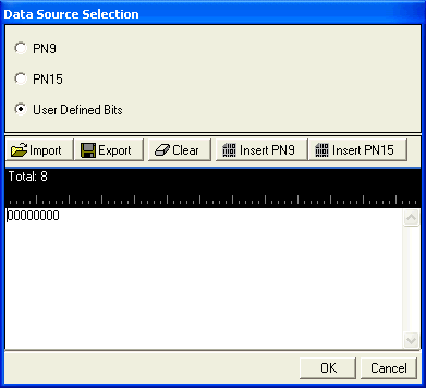
  Data Source Selection
window. Enter the bits to use in the first of the two tail bit segments
of the burst.

Import
 Click to open a dialog
box in which you can navigate to and import a pre-defined pattern file.
The imported file automatically updates the user data entry area. The
software accepts the following file types:
The
maximum file size is 65536 bits. If the imported file is larger than 65536
bits, the software truncates the bits to conform to the maximum file size.
Export
 Click to open a dialog
box in which you can save the current data pattern to a file. You can
save the data pattern as one of the following file types:
Clear
 Click
to clear all data displayed in the user data entry area.
Insert PN9
 Click to insert a fixed
psuedo-random bit sequence (pattern) containing 511
bits (29-1) into the user
data entry area. The software generates this fixed pattern in accordance
with the CCITT recommendation 0.153. You can click
this button repeatedly to add additional PN9 sequences until the maximum
file size is reached (65536 bits). If the maximum
file size is exceeded, the software truncates the excess data.
To edit the existing data pattern after reaching
the maximum file size, insert the cursor at the desired point in the file
and press or use the
keyboard 1 and 0 keys. The software inserts the data at the cursor position
and truncates data in excess of 65536 bits.
Insert PN15
 Click to insert a
fixed pattern psuedo-random bit sequence containing
32,767 bits (215-1) into the
user data entry area. The software generates this fixed pattern in accordance
with the CCITT recommendation O.153.
To edit the data pattern, insert the cursor at the
desired point in the file and click Insert PN15, or enter the information
manually using the keyboard keys 1 and 0. The software inserts the data
at the cursor position and truncates all data in excess of 65536 bits.
-
UBS-6 uses 8-bits
-
UBS-8 uses 16-bits
-
UBS-11 uses 20-bits
Header Data
Choice: RANDOM| PN9 |
PN15 | User Defined Bits
Default: RANDOM
Double-click or use the  drop-down
menu to set the
  Header
Data.

(Refer to 3GPP 44060-610 section 10.0a.2)
The "RANDOM" value, refers to being in
a given range, or more generally with some statistical distribution. The
use of RANDOM Header Data is only used in the Mobile Station measurements.
Refer to 3GPP 44.018.
Data
Click the Details button  in this cell to open the
  Data Source
Selection
window.
Select an encoded ,
or .
The selected data is coded continuously across the RLC data block per
the 3GPP standards. An independent version of the selected data is coded
across the unused RLC/MAC header fields.

Import
 Click to open a dialog
box in which you can navigate to and import a pre-defined pattern file.
The imported file automatically updates the user data entry area. The
software accepts the following file types:
The
maximum file size is 65536 bits. If the imported file is larger than 65536
bits, the software truncates the bits to conform to the maximum file size.
Export
 Click to open a dialog
box in which you can save the current data pattern to a file. You can
save the data pattern as one of the following file types:
Clear
 Click
to clear all data displayed in the user data entry area.
Insert PN9
 Click to insert a fixed
psuedo-random bit sequence (pattern) containing 511 bits (29-1)
into the user data entry area. The software generates this fixed pattern
in accordance with the CCITT recommendation 0.153. You can click this
button repeatedly to add additional PN9 sequences until the maximum file
size is reached (65536 bits). If the maximum file
size is exceeded, the software truncates the excess data.
To edit the existing data pattern after reaching
the maximum file size, insert the cursor at the desired point in the file
and press or use the
keyboard 1 and 0 keys. The software inserts the data at the cursor position
and truncates data in excess of 65536 bits.
Insert PN15
 Click to insert a
fixed pattern psuedo-random bit sequence containing 32,767 bits (215-1) into the user data entry area.
The software generates this fixed pattern in accordance with the CCITT
recommendation O.153.
To edit the data pattern, insert the cursor at the
desired point in the file and click Insert PN15, or enter the information
manually using the keyboard keys 1 and 0. The software inserts the data
at the cursor position and truncates all data in excess of 65536 bits.
Training Sequence Bits (nn
bits)
Choice: TSC0 to TSC7
or User Defined Bits
Default: TSCO
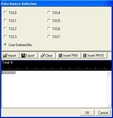
Click the Details button  in this cell to open the
  Data Source Selection
window.
Select to
or to use for the training sequence bits.
If you manually change a timeslot (channel type), the training sequence
for that timeslot resets to provided
that the training sequence was not previously changed for the new channel
type.
Select to define  custom training sequence
bits.
The buttons in this window are described in Data.

The training sequences selections are defined as
follows:
-
 UBS-6 (62-bits)
|
TSC0
|
0C30 33FF F0CF F0FC
|
|
TSC1
|
3F0F 03FF 33CC 0C30
|
|
TSC2
|
30FC FC33 CFFC 0CC0
|
|
TSC3
|
003F 000C 3F33 C330
|
|
TSC4
|
330F C0F3 C33F FF30
|
|
TSC5
|
0330 F33F 0C00 3F00
|
|
TSC6
|
33FF CF30 3F3C 0FCC
|
|
TSC7
|
33FF 3CCF C03C FCF0
|
-
 UBS-8 (124-bits)
|
TSC0
|
3F3 3F33 3F3F FFFF FF33 F3FF FF33 FFF3
|
|
TSC1
|
FFF 33FF 333F FFFF 3F3F F3F3 33F3 3F33
|
|
TSC2
|
F33 FFF3 FFF3 3F3F F3FF FFF3
33F3 F333
|
|
TSC3
|
333 3FFF 3333 33F3 3FFF 3F3F F33F 3F33
|
|
TSC4
|
F3F 33FF F333 FF3F F33F 3FFF FFFF 3F33
|
|
TSC5
|
33F 3F33 FF3F 3FFF 33F3 3333 3FFF 3333
|
|
TSC6
|
F3F FFFF F3FF 3F33 3FFF 3FF3 33FF F3F3
|
|
TSC7
|
F3F FFFF 3FF3 F3FF F333 3FF3 FFF3 FF33
|
-
 UBS-11
(155-bits)
|
TSC0
|
481 2902 5290 2400 0000 0025 2048 0000 2520 0012
|
|
TSC1
|
000 0948 0094 A400 0000 9024 0048 1294 8129 0252
|
|
TSC2
|
025 2000 1200 0129 0240 0480 0000 1294 8120 4A52
|
|
TSC3
|
4A5 2900 0094 A529 4812 9000 0902 4004 A409 0252
|
|
TSC4
|
024 0948 0004 A520 0240 04A4 0900 0000 0009 0252
|
|
TSC5
|
4A4 0902 5200 2409 0000 9481 294A 5290 0009 4A52
|
|
TSC6
|
024 0000 0004 8009 0252 9000 0900 1294 8000 4812
|
|
TSC7
|
024 0000 0090 0120 4800 04A5 2900 1200 0120 0252
|
Tail Bits 2 (nn
bits)(nn bits entry)
Default (UBS-6): X"1E"
Default (UBS-8): X"166D"
Default (UBS-11): X"F79CE"
Click the Details button  in this cell to open the Data Source Selection.
 Enter the bits
to use in the second of the two tail bit segments of the burst.
-
UBS-6 uses 8-bits
-
UBS-8 uses 16-bits
-
UBS-11 uses 20-bits
Guard Period (nn
bits) (nn bits entry)
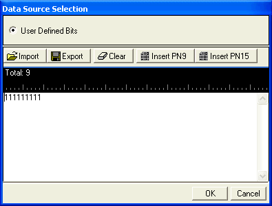
Default (UBS-6): X"FFFFFF"
Default (UBS-8): X"FFFFFFFFFFFF"
Default (UBS-11): X"FFFFFFFFFFFFFFF"
Click the Details button  in this cell to open the
  Data Source Selection
window.
-
UBS-6 requires an entry
of 24-bits
-
UBS-8 requires an entry
of 48-bits
-
UBS-11 requires an entry
of 60-bits
E and FBI/TI
Choice: On | Off
Default: Off
Double-click or use the drop-down menu to set the
state. Sets the Extension (E) bit and either the Final Block Indicator
(FBI) bit in the downlink or the TTLI Indicator (TI) bit in the uplink
(See  E and FBI/TI data block structure).

Figure: Components of the EGPRS RLC data
block. (Refer to 3GPP 44.060, section
10.3a.)
2. Control Frame
Data for Control Frame
Set the data for the control frame within a multiframe
setup. Click the Details button  in this cell to open the
  Data Source Selection
window.
Select ,
or . Select to  create
a data string.
If the Multiframe
type parameter at the Carrier n node is set to , the parameter, while appearing as active, has no
effect since there is no control frame.
Related Topic
Timeslot
(Advanced)


 to display a drop-down menu in which you can copy a timeslot configuration
from one timeslot to another.
 in this cell to open the
  Data Source Selection
window. Enter the bits to use in the first of the two tail bit segments
of the burst.
  drop-down
menu to set the
  Header
Data.
 in this cell to open the
  Data Source
Selection
window.
  in this cell to open the
  Data Source Selection
window.
 custom training sequence
bits.
 in this cell to open the Data Source Selection.
 Enter the bits
to use in the second of the two tail bit segments of the burst.
  in this cell to open the
  Data Source Selection
window.
  E and FBI/TI data block structure).
 in this cell to open the
  Data Source Selection
window.
  create
a data string.