Using one of the two  examples
--or create your own-- set up the N7602B software to generate a Control
Channels waveform.
Examples of Standard BCH (Control Channels) and Waveform Pre-configurations
The order of the Carrier setups is optional.
Example 1: FCCH + SCH + BCCH + CCCH and GSM BCH + TCH/FS + PDTCH Pre-Configuration
FCCH + SCH + BCCH + CCCH Waveform Setup Requirements
|
Tree View Node |
Parameter: Configuration or Channel Type (Radio Format) |
|---|---|
|
Waveform Setup1 |
GSM BCH + TCH/FS + PDTCH |
|
WFMn |
No action is required. |
|
Carrier 1 |
Control Channels (1.GSM/EDGE): FCCH + SCH + BCCH + CCCH |
|
Timeslot |
Standard Combined BCH (on TS0)2 |
|
Carrier 2 |
Advanced GSM/EDGE/EGPRS2-A (1.GSM/EDGE): TCH/FS 1 Timeslot On TS3 and PDTCH 1 Timeslot On TS4 |
|
Timeslot |
|
1 Use the Insert New Waveform button to select the correct WFMn. type. The software then selects the default Carriers for this waveform.
2 Verify TS3 and TS4 states are off.
3 Optional: Choose one of the Coded Downlink or Uplink MCS-5 to MCS-9 (PDTCH) data types (Software defaults to Coded Downlink MCS-5).
4 Verify TS3 and TS4 are on.
Example 2: FCCH + SCH + BCCH + CCCH + SDCCH + SACCH and GSM BCH + TCH/HR + PDTCH Pre-Configuration
FCCH + SCH + BCCH + CCCH + SDCCH + SACCH Waveform Setup Requirements
|
Tree View Node |
Parameter: Configuration or Channel Type (Radio Format) |
|---|---|
|
Waveform Setup1 |
GSM BCH + TCH/HS + PDTCH |
|
WFMn |
No action is required. |
|
Carrier 1 |
Control Channels (1.GSM/EDGE): FCCH + SCH + BCCH + CCCH + SDCCH + SACCH2 |
|
Timeslot |
Standard Combined BCH (on TS0)3 |
|
Carrier 2 |
Advanced: Half Rate GSM/EDGE/EGPRS2-A: (1. GSM/EDGE): TCH/HS 1 Timeslot On TS3 |
|
Timeslot |
Coded TCH/HS (on TS3)4 |
|
Carrier 3 |
Advanced GSM/EDGE/EGPRS2-A (1. GSM/EDGE): PDTCH 1 Timeslot On TS4 |
|
Timeslot |
Coded Downlink MCS-5 (on TS4)5,6 |
1 Use the Insert New Waveform button to select the correct WFMn. type.
2 Use the Configuration parameter's dropdown to select this BCH.
3 Verify TS3 and TS4 states are off. If not, use the State parameter's down arrow to turn off.
4 Verify TS3 is on.
5 Verify TS4 is on.
6 Optional: Choose one of the Coded Downlink or Uplink MCS-5 to MCS-9 (PDTCH) data types (Software defaults to Coded Downlink MCS-5)
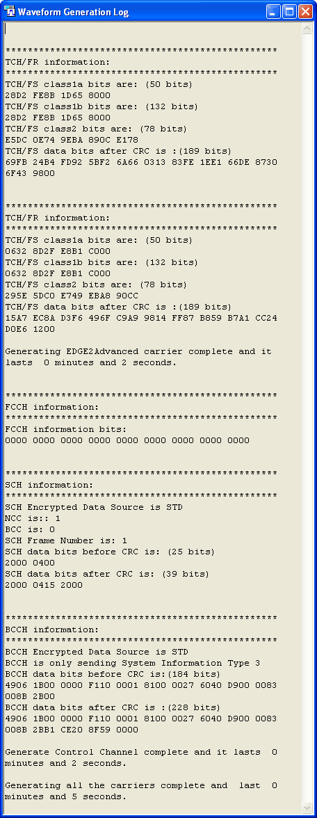
In the Tool menu, click Waveform Generation Log to open the window.
Click the Generate
button  to create a waveform. The transport layer information appears
in the window, as shown.
If you open the Waveform Generation Log after generating a waveform, no information is displayed.
