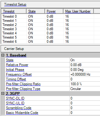

This table enables you to view the key parameters for each timeslot. Double-clicking a row activates the setup tables for that timeslot.
Displays the number of the selected timeslot. The parameters you set apply to this timeslot.
Choice: On | Off
Default: On
Double-click or use the drop-down menu to set the state of the timeslot or .
Range: –60 to 0 dB.
Default: 0 dB
Display the timeslot power. The CDP graph displays the normalized power of each RU in each timeslot after you generate the waveform. Refer to the Power Setting for the power calculation of the carriers, channels/timeslots and RUs.
Range: 2 to 16
Step: 2
Default: 16
Enter a value to set a max user number for the selected timeslot.
Choice: On | Off
Default: On
Double-click or use the drop-down menu to set the state of the carrier or .
Range: -60 to 0 dB
Default: 0 dB
Set the carrier's power relative to the signal generator's amplitude setting. Refer to the Power Setting for the power calculation of the carriers, channels/timeslots and RUs.
Range: –180 to 180 degrees
Default: 0.00 deg
Set the initial phase of the carrier.
Range: –16 to 16 MHz
Default: 0 Hz
Set the frequency offset of the carrier relative to the signal generator's frequency setting.
This parameter is coupled with the Oversampling Ratio.
Range: 0 to 377
Default: 0
Set the timing offset of the carrier. Timing offset values increment by 16 chips.
Range: 10% to 100%
Default: 100%
Enter a value to set the pre-filter clipping ratio for the carrier.
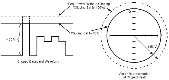
Digitally modulated signals with high power peaks can cause intermodulation distortion, resulting in spectral regrowth that can interfere with signals in adjacent frequency bands. The clipping function enables you to reduce high power peaks by clipping the I and Q data to a selected percentage of its highest peak, thereby reducing spectral regrowth.
Range: Rectangular | Circular
Default: Circular
Double-click or use the drop-down menu to set the pre-filter clipping type for the carrier.
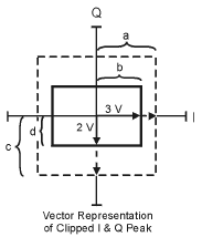
is applied to the composite I/Q data (I and Q data are equally clipped). As shown below, the clipping level is constant for all phases of the vector and appears as a circle in the vector representation.
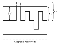
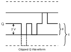
is independently applied the I and Q data. As shown in below figure, the clipping level is different for I and Q, and appears as a rectangle in the vector representation.
Range: 0 to 31
Default: 0
Double-click or use the drop-down menu to set the downlink synchronization code.
Range: 8 * SYNC-DL ID to 8 * SYNC-DL ID + 7
Default: 0
Double-click or use the drop-down menu to set the uplink synchronization code. SYNC-UL ID belongs to the code group determined by the SYNC-DL ID.
Range: 4 * SYNC-DL ID to 4 * SYNC-DL ID + 3
Default: 0
Enter a value to set the scrambling code of the carrier. Scrambling code should be equal to the basic midamble code and belong to the code group determined by the SYNC-DL ID.
Range: 4 * SYNC-DL ID to 4 * SYNC-DL ID + 3
Default: 0
Enter a value to set the basic midamble code of the carrier. Scrambling code should be equal to the basic midamble code and belong to the code group determined by the SYNC-DL ID.