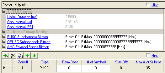

Displays the uplink duration in milliseconds, set in Waveform Setup.
Displays the size of the RTG in microseconds. You cannot edit this cell.
Displays the size of the RTG gap in PS units. You cannot edit this cell.
1 PS = 4/Fs per section 10.3.4.2 in 802.16Rev2/D6
The following settings are only available When Output Mode is set to Downlink Only (FDD/H-FDD) or Uplink Only (FDD/H-FDD).
Displays the subframe duration in milliseconds.
Displays the size of the unused interval of uplink subframe in microseconds
Displays the size of the unused interval of uplink subframe in symbol units. You cannot edit this cell.
Range: 0x000000000000000000 to 0x3fffffffffffffffff [Hex]
Set the uplink subchannels bitmap of PUSC Zone.
Choice: On, Off
Double-click or use the drop-down menu to set the state of the PUSC Subchannels Bitmap.
Range: 0x00 to 0xff
Set the uplink bitmap byte.
Range: 0x00000000000000000000000000 to 0x00ffffffffffffffffffffffff [Hex]
Set the uplink subchannels bitmap of OPUSC Zone.
Choice: On, Off
Double-click or use the drop-down menu to set the state of the OPUSC Subchannels Bitmap.
Range: 0x00 to 0xff [Hex]
Set the uplink bitmap byte.
Range: 0x000000000000 to 0xffffffffffff
Set the uplink physical bands bitmap of the AMC Zone.
Choice: On, Off
Double-click or use the drop-down menu to set the state of the AMC Physical Bands Bitmap.
Range: 0x00 to 0xff [Hex]
Set the uplink bitmap byte.
Use the Add Button  to add a new uplink zone type to the frame configuration
from the pull-down menu. When a zone is added, the software inserts the
zone (up to eight) in the tree view and adds it to the frame plot view.
Use the Delete Button  to delete the selected zone. The zone to
be deleted is indicated by the
  in the first column. The first PUSC zone
cannot be deleted.
Use the Copy Button  to add a new zone that has the same configuration
as the currently selected one (indicated by the
  in the first column).
Use the Up and Down arrows  to reposition the currently selected zone
(indicated by the
  in the first column).
Displays the zone index number.
Choices: PUSC, OPUSC, AMC, Sounding
PUSC = partial usage of subchannels
OPUSC = optional partial usage of subchannels
AMC = adaptive modulation and coding (AMC 2x3 zones are supported.)
Sounding = Create uplink signal with sounding zone and sounding messages with various values for Max Cyclic Shift Index (P) and Decimation Value (D) with equal power assignment to all pilots.
Displays the zone type selected from the  drop-down
menu.
Range: 0 to 69
Specifies the uplink permutation base.
Specify the number of symbols in this zone. See also Number of Symbols.
Displays how much the zone is offset from the beginning of the downlink subframe. The symbol offset displayed includes the default preamble (1 symbol).
Displays the maximum number of subchannels per symbol for the zone configuration. See also Max. Number of Subchannels.