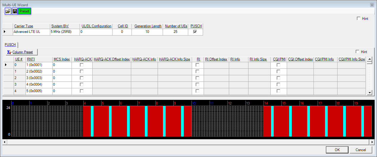
This window provides all the functions necessary to configure a multi-UE waveform and is accessed by clicking the button in the Waveform Setup screen. When you have finished your configuration, click and a small ![]() progress window appears briefly as the software checks for resource block conflicts. An error message reports the details should any conflicts occur. Otherwise, the configuration is valid.
progress window appears briefly as the software checks for resource block conflicts. An error message reports the details should any conflicts occur. Otherwise, the configuration is valid.

Opens a multi-UE settings file (*.mus). Also supports *.txt and *.csv file formats. Refer to Importing and Exporting Multi-UE Settings Files for more information.
Saves your current configuration to a multi-UE settings file (*.mus). Also supports *.txt and *.csv file formats. Refer to Importing and Exporting Multi-UE Settings Files for more information.
Presets the multi-UE wizard to the default configuration.
Displays the UL carrier that is fixed at Advanced LTE UL.
Choice: 1.4 MHz (6RB) | 3 MHz (15RB) | 5 MHz (25RB)) | 10 MHz (50RB) | 15 MHz (75RB) | 20 MHz (100RB)
Default:
LTE: 5 MHz (25RB)
LTE-A: 10 MHz (50RB)
Double-click or use the drop-down menu to set the system bandwidth and number of resource blocks (RB). When you select a system bandwidth, the software automatically adjusts the values in the Total Number of Resource Blocks and Total Number of Occupied Sub-carriers cells.
Advanced LTE and LTE-A carriers only: When the system bandwidth is decreased, the DL-SCH Tx Sequence window's RB size, and some of the other data channel's settings, are reconfigured, similar to when a predefined configuration is executed. But, when the system bandwidth is increased, no change to the DL-SCH Tx Sequence window's RB size, or the other data channel's settings occurs.
Range: 0 to 6
Default: 0
Coupling: For Basic, Advanced UL, and Advanced DL LTE-A TDD when Auto Carrier Aggregation Configuration is set to On, this setting is read only for the secondary cells that has the same value as the primary cell.
Double-click or use the drop-down menu to select the uplink-downlink configuration.
The supported uplink-downlink configurations are defined in Table 4.2-2 of 3GPP TS 36.211.
In the case of intra-band carrier aggregation, the PCell parameter is editable, but SCell is read-only. With inter-band carrier aggregation, both parameters are editable.
The resource blocks and some parameters are reconfigured by changing the Uplink Downlink Configuration parameter in the same manner as Predefined Configuration.
Range: 0 to 503
Default: 0 with Auto Carrier Aggregation Configuration set to Off
Same as the CC index number with auto Carrier Aggregation Configuration set to On
With Auto Carrier Aggregation Configuration set to Off, enter a Cell ID value.
The software uses this value to set the Physical Layer Cell ID group and sector cells:
Cell ID = (3 x Physical Cell ID group + Physical Cell ID sector).
See 3GPP TS 36.211 for more information.
Range: 10 ms to 160 ms
Default: 10 ms
Enter a value of waveform generation length.
Range: 1 to 100
Default: 25
Enter a number of UEs signal for Multi-UE Generation.
Displays the PUSCH state. A check mark indicates the channel is on.
This table shows the configurations for each individual UE. UE parameters can be set independently or globally, using Column Preset.
This button opens a drop-down menu, allowing you to select a global setting for a certain UE parameter.
Displays the UE number.
Range: 0 to 65535
Default: 0
Enter a value for the Radio Network Temporary Identifier (RNTI).
Choice: Off | 0 | 1 ..... 26 | 27 | 28
Default: 0
Double-click or use the drop-down menu to set the MCS index of MCH. In case of MCS Index = 0 to 28, both parameters Modulation and TBS Index are automatically decided by software. In case of MCS Index = Off, both parameters Modulation and TBS Index are selectable by user. For more detail, refer to 3GPP TS 36.212, 36.213 and 36.331.
Choice: On | Off
Default: Off
Sets HARQ-ACK state on or off.
Range: 0 to 15
Default: 0
Enter a value for the HARQ-ACK Offset Index.
Choice: ACK | NACK | ACK-ACK | ACK-NACK | NACK-ACK | NACK-NACK | User Defined Bits (Up to 0 to 20 Bits)
Default: ACK
Sets HARQ-ACK Information. If User Defined Bits is selected, Bit sequence containing "0" or "1" up to 20 bits is available. "1" means ACK. "0" means NACK.
Range: 1 to 20
Specifies HARQ-ACK Information Size. If HARQ-ACK Info is set User Defined Bits, HARQ-ACK Information Size is available to set up to User Defined Bits length. Otherwise it is read only.
Choice: On | Off
Default: Off
Sets RI state on or off.
Range: 0 to 12
Default: 0
Enter a value for the RI Offset Index.
Choice: 0 | 1 | 0-0 | 0-1 | 1-0 | 1-1 | User Defined Bits (Up to 0 to 15 Bits)
Default: ACK
Sets RI Information. If User Defined Bits is selected, Bit sequence containing "0" or "1" up to 15 bits is available.
Range: 1 to 15
Specifies RI Information Size. If RI Info is set User Defined Bits, RI Information Size is available to set up to User Defined Bits length. Otherwise it is read only.
Choice: On | Off
Default: Off
Sets CQI/PMI state on or off.
Range: 2 to 15
Default: 2
Enter a value for the CQI Offset Index.
Choice: PN9 | PN15 | User Defined Bits
Default: PN9
Sets CQI/PMI Information.
Range: 1 to 144
Specifies CQI/PMI Information Size.
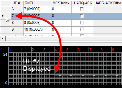
Displays how resource blocks are allocated for a specific UE. Click the blank cell to the left of the UE # you want to see in the graph. If you right-click anywhere in the row of the selected UE, a ![]() Set Selected UEs Transmission button appears. Clicking this button opens the
Set Selected UEs Transmission button appears. Clicking this button opens the ![]() UE #n PUSCH Tx Sequence editor for the UE, allowing you to set subframe states and resource block offsets and sizes. To show the RB allocation for all the UEs, click the blank cell to the left of Carrier Type in the upper table of the wizard.
UE #n PUSCH Tx Sequence editor for the UE, allowing you to set subframe states and resource block offsets and sizes. To show the RB allocation for all the UEs, click the blank cell to the left of Carrier Type in the upper table of the wizard.
