The appearance of this dialog changes slightly between two pulse measurement types: Standard Pulse and Pulse Profile, as shown below. Additionally, the dialog can be switched between Basic and Advanced modes.
The dialog comprises four groups of properties for pulse configuration:
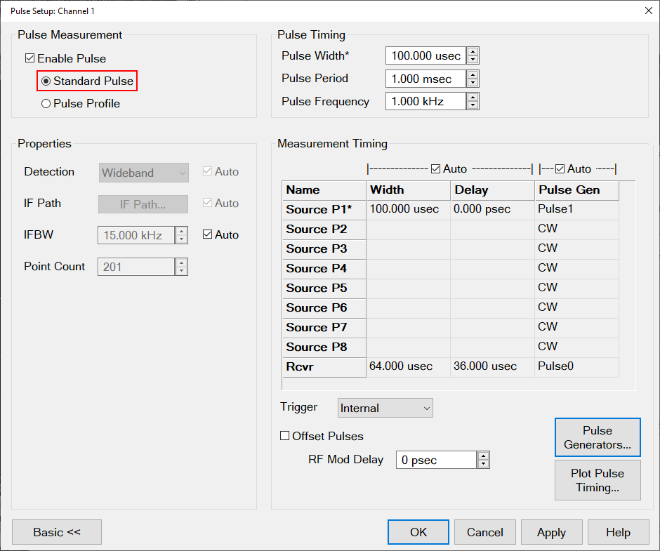
Standard Pulse (PXI)
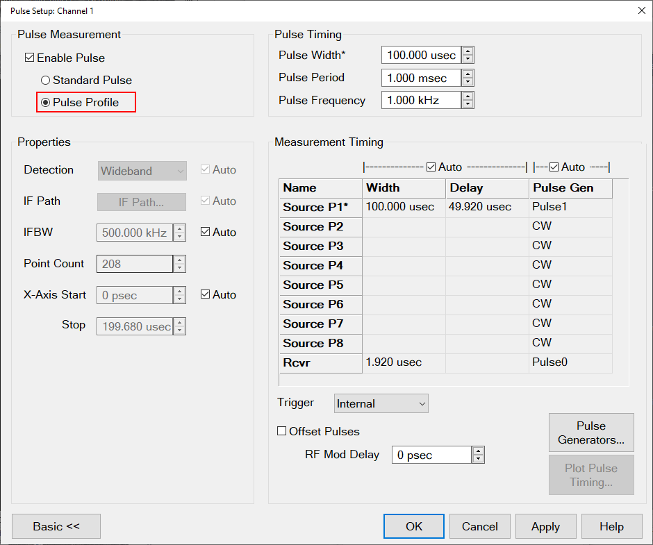
Pulse Profile (PXI)
Basic and Advanced Modes
Basic mode settings appear when you first open the dialog. Clicking the Advanced >> toggle button expands the dialog to access additional pulse settings. Click Basic << to hide the advanced settings.
Basic mode controls simple pulse measurements, using the default (auto-selected) settings in the Advanced section of the dialog.
Advanced mode accesses the additional settings, providing you maximum control of a pulse measurement configuration.
Pulsed Profile measurements are performed in a Standard channel. (See Measurement Class.) Standard Pulse measurements are supported by most channel types.
Several VNA measurement settings are controlled by Pulse Setup, such as sweep type, number of points, and so forth..
Pulse Measurement
Note: (M980xA, P50xxA/B) Fast mode for pulse modulation in the data sheet can be set by the SENSe:SWEep:PULSe:SHAPe.
Enable Pulse (checkbox)
When enabled, the source and receivers are pulsed. The default state is disabled (not checkmarked). The Standard Pulse and Pulse Profile radio buttons remain selectable in either state.
Standard Pulse (radio button)
This measurement type is selected by default. With pulsed RF, the VNA can be configured to sweep in frequency, power sweep, and CW time. This measurement type is used for Point-in-Pulse measurements and Pulse-to-Pulse measurements.
Pulse Profile (radio button)
Pulse profile measurements provide a time-domain (CW frequency) view of the pulse envelope. Profiling is performed using a measurement technique that "walks" a narrow receiver "snapshot" across the width of the pulse. This is analogous to using a camera to take many small snapshots of a wide image, then piecing them together to form a single, panoramic view. (This function is available in standard class only.)
Pulse Profile measurement using default settings and R1 receiver.
-
Pulse Profiling can be performed using ratioed or unratioed measurements. You can preview the pulse on port 1 by using an R1 receiver measurement.
-
Pulse Profiling is performed at a single CW frequency in Wideband mode.
-
To select the CW Frequency, click Stimulus, then Sweep Type.
-
In Wideband mode, the receiver is walked across the pulse by making a sequence of closely-spaced measurements in real-time.
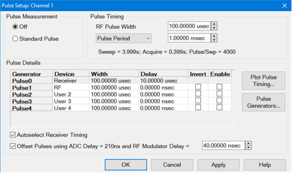
Pulse Timing
Pulse Width
Defines the width of the RF pulse. See measurement timing to learn how to control the receiver width and delay.
In Advanced mode (expanded), the label "Pulse Width" will include an asterisk *. This value is linked to the pulse width of the modulating source, which will also be indicated with an asterisk * in the timing table.
Pulse Period
Defines the period (i.e. one complete pulse) of the pulse train.
Pulse Frequency (PFR)
The reciprocal of Period (1/ Period). See Internal Pulse Generators to learn more.
Properties
Detection
This function is not available. Only Wideband is available in M9485A, M980xA, M983xA, P50xxA/B.
For Standard Pulse:
The VNA will select Wideband any time the RF pulse width is longer than the shortest receiver acquisition time, which is approximately the reciprocal of the widest available IFBW with some added margin.
For Pulse Profile:
The VNA will select Wideband any time the RF pulse width is longer than the shortest receiver acquisition time multiplied by 6, which is approximately the reciprocal of the widest available IFBW multiplied by 6.
IF Path
Auto is Enabled by default. To manually change the IF Path settings, uncheck the Auto checkbox and click the "IF Path..." button to open the IF Path dialog.
IFBW
Auto is Enabled by default.
When Auto is enabled in Standard Pulse mode:
-
For Wideband detection mode the IFBW with the longest acquisition time that fits within the specified RF pulse width, with some margin, is selected.
When Auto is enabled in Profile Pulse mode:
-
For Wideband detection mode an IFBW is selected based on RF pulse width. VNA chooses an IFBW whose acquisition time results in a profile sweep with a point count around 201.
Point Count
Displays the read-only point count that will be set when the settings are applied.
X-Axis Start/Stop
This property is only available in Pulse Profile mode.
Auto is Enabled by default.
If Auto is selected, the VNA will automatically change the X-axis start and stop times so that the profile is centered on the screen and occupies 50% of the screen.
If Auto is not selected, the start and stop times may be manually specified.
Note: The X-Axis timing values are affected by the "Rcvr ADC Delay" and "Nominal RF Mod Delay" values.
Measurement Timing
Table Properties
Source (Rows)
These rows control the modulators associated with each source or source port. Source rows whose names contain an asterisk * have width values that are coupled to the Pulse Width property in the Pulse Timing panel.
Recv (Rows)
In Wideband detection mode these rows control the receiver timing. The receivers can only be driven by Pulse0.
Width and Delay (Columns)
Auto is enabled by default.
When Auto is enabled, the widths and delays will be automatically chosen by the VNA.
In Standard Pulse mode:
-
For the Wideband detection mode, the receiver width represents the acquisition time of an automatically chosen IFBW. The IFBW with the longest acquisition time that fits within the specified RF pulse width, with some margin, is selected. The receiver delay is chosen to align the receiver trigger (Pulse0) with the RF pulse, accounting for the specified RF delay.
To manually change the widths or delays, uncheck the Auto checkbox to enable the cells in these columns.
Pulse Gen (Column)
Auto is enabled by default.
While Auto is enabled the VNA will select Pulse1 to drive all source modulators and Pulse2 to drive all IF gates.
To manually specify which pulse generator drives each row, uncheck the Auto checkbox to enable the cells of this column.
In addition to the internal pulse generators, other pulse generator selections are available:
-
CW – Drives the row with a continuous ‘High’ signal.
-
External – Drives the row with an external generator being defined in the External Device dialog. For “Source” rows the signal provided to the “RF Pulse Mod In” IO is used. For “Recv” rows the signal provided to the “IF Gate A In”, “IF Gate B In”, “IF Gate C In”, and “IF Gate D In” are used to drive the corresponding IF gate.
-
Other external generators that have been defined in the External Device dialog.
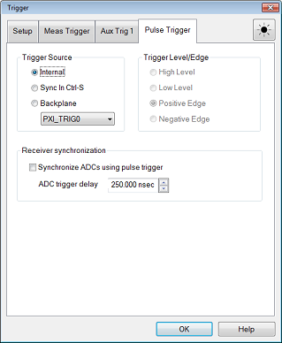
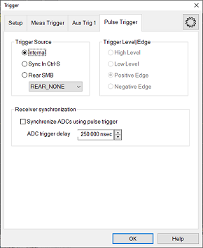
Trigger
Note: This provides the same selections as provided in the Pulse Generators Setup dialog and the Trigger dialog on its "Pulse Trigger" tab.
This combo box allows you to select the pulse trigger source. Choices include the following:
-
Internal - Uses the internal pulse generator clock.
-
External - Uses the external RFPulseModIn input. The source of the signal is not defined, so the user must set it independently.
-
PXI_TRIG0 through PXI_TRIG7 - allows the backplane PXI trigger lines to be used when using a PXI-based instrument.
-
MyPulseGen - The names of pulse generators set up as External Devices appear in this combo box. If chosen, then it is assumed to be connected to the external RFPulseModIn connector.
-
Trigger... - This last selection in the combo box opens the Trigger dialog on the Pulse Trigger tab. This is for user convenience for defining other pulse trigger features.
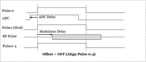
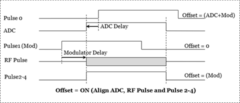
Offset Pulse Delays Using (checkbox)
This checkbox is also found in the Pulse Generators Setup dialog.
Disabled by default.
When enabled, the Nominal RF Mode Delay and Rcvr ADC Delay may be subtracted from the delay values displayed.
The delay terms compensated for in this subtraction depends on the position of the element in the signal processing chain that this pulse generator is driving. For example, pulse generators driving modulators have no delay subtracted, but a pulse generator driving ADC triggering (Pulse0) will have the Nominal RF Mode Delay and Rcvr ADC Delay subtracted from its delay.
Modulator Delay
This is the approximate delay of the RF modulator.
This value is always active and may be changed as needed.
If "Auto Width and Delay" is enabled, this will be used to automatically set the delay.
If "Offset Pulse Delays Using" is enabled, this will be used to offset the delay values in the table.
ADC Delay
This is the delay of the receiver ADCs.
This value is fixed and cannot be changed.
If "Auto Width and Delay" is enabled, this will be used to automatically set the delay.
If "Offset Pulse Delays Using" is enabled, this will be used to offset the delay values in the table.
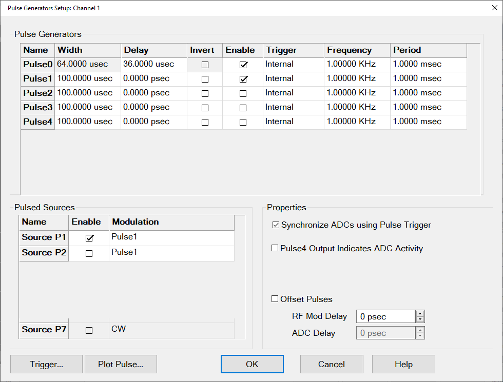
Pulse Generators... (button)
This button is only available if Pulse is enabled.
Opens the Pulse Generators Setup dialog.
Plot Pulse Timing... (button)
This button is only available if Pulse is enabled.
Accesses the Pulse Timing dialog with an interactive screen, displaying pulse characteristics in the time domain.
This dialog is accessed from both the Pulse Setup and Pulse Generators Setup dialogs.
Right-click on the display area to access the menu selections described below:
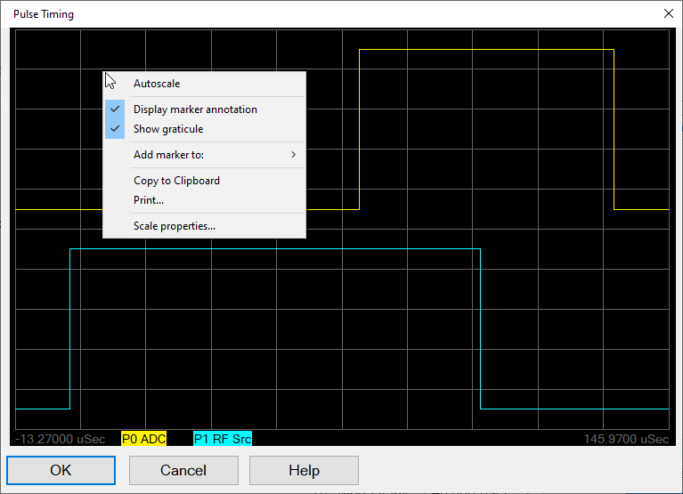
Autoscale - Automatically scales the data to fit vertically within the display grid area.
Display marker annotation - Select to display marker annotation in the top-right of the display.
Show graticule - Select to display the graticule.
Add marker to: - Select to add a marker to a displayed pulse trace. When a selection is made, the mouse pointer changes to a "+". Click in the display area and the marker will appear. Drag the marker to the desired position. Each time this selection is made, a new marker will be added.
Copy to Clipboard - Copies a bitmap of the trace control (Display) to the clipboard. It can then be pasted into any document that accepts bitmaps.
Print... - Prints the displayed data.
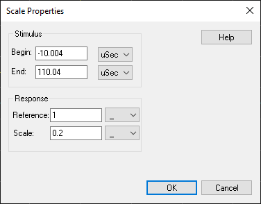
Scale properties... - Accesses the Scale Properties dialog:
Stimulus - Sets the Begin and End displayed on the X-axis in seconds.
Response - Sets the Reference level in the center of the Y-axis and sets the scale per division.