Receiver Gain
The receiver gain can be fixed on the M98xxA and P50xxA/B. When the receiver gain is lower than expected, for example due to an unexpected spurious signal, this function allows you to fix the gain level to improve the dynamic range. The measurement speed is almost the same even if the range is fixed.
Note: Receiver Gain for P937xB always set at LOW.
How to make Receiver Gain settings
Use one of the following methods to set port power. The softkey is available on standard measurement class only.
|
|
Using Hardkey/SoftTab/Softkey
|
Using a mouse
|
-
Press Setup > Internal Hardware > Receiver Gain.... or Rcvr Gain Mode
|
-
Click Instrument > Setup > Internal Hardware> Internal Hardware > Receiver Gain... or Rcvr Gain Mode
|
|
Programming Commands
|
If the gain is automatic, or varies by source port, calibration will take place in multiple gain settings. The analyzer has the independent error terms for high and low receiver settings. Each error terms can be monitored in Cal Set Viewer. Error terms with square brackets refer to high [1] or low [0] settings. Error terms without any square brackets refer to the low gain. When calibration is acquired in the high gain setting, a maximum power of -25 dBm will be used.
Note: The wideband/reference calibration set must have the same switched gain settings as the user cal set.
Calibration Time Reduction (Fixed Gain Calibration)
When receiver gain settings includes AUTO or combination of High and Low, the analyzer measures the error terms for both high and low settings automatically. Hence, the analyzer make sweeps three times in the calibration.
When receiver gain settings are all FIXED (high or low) and have same state for each source port, the VNA takes sweep for the calibration only one time for specified gain setting in order to reduce the calibration time.
For example, the following setting can reduce the calibration time.
|
Receiver gain setting
|
Receiver port
|
|
1
|
2
|
3
|
4
|
|
Source Port
|
1
|
Low
|
High
|
Low
|
High
|
|
2
|
Low
|
High
|
Low
|
High
|
|
3
|
Low
|
High
|
Low
|
High
|
|
4
|
Low
|
High
|
Low
|
High
|
|
Receiver gain setting
|
Receiver port
|
|
1
|
2
|
3
|
4
|
|
Source Port
|
1
|
Low
|
High
|
High
|
High
|
|
2
|
Low
|
High
|
High
|
High
|
|
3
|
Low
|
High
|
High
|
High
|
|
4
|
Low
|
High
|
High
|
High
|
Receiver Overload / ADC Overflow
When the receiver gain is set at Auto, the pre-measurement is done to select the proper range (HIGH or LOW). SENSe<cnum>:SOURce<sport>:RECeiver<rport>:GAIN:LIST? returns the information which range is used at each test point.
The receiver overload/ADC overflow may occur in the following conditions when the receiver gain is set at HIGH (including HIGH in AUTO setting)
Receiver overload can be turned off in the preference.
M983xA Gain Coupling and M983xA/M980xA Receiver Gain Control for Application
|
Application
|
Receiver Gain Control
|
Gain Coupling
(M983xA only)
|
RF Atten and IF Gain Control
(M983xA only)
|
Note
|
|
Standard
|
Available
|
Available
|
Available
|
|
|
Pulse measurement
|
Available
|
Available
|
Available
|
Receiver Gain is set at LOW internally when AUTO
|
|
FOM
|
Available
|
Available
|
Available
|
Receiver Gain is set at RF:LOW, IF:AUTO internally when AUTO
|
|
Noise Figure, Noise Figure Converter in Noise Path (Bypass)
|
-
|
-
|
-
|
High/Medium/Low in Noise Figure dialog box
|
|
Noise Figure, Noise Figure Converter in S parameter
|
Disabled
|
Always off "Manual"
|
Available
|
|
|
Spectrum Analysis, Modulation, Modulation Converter
|
Disabled
|
Always off "Manual"
|
Available
|
|
|
SMC, SMC+Phase, Gain Compression, Gain Compression Converter, Active Hot Parameter
|
Disabled: Fixed at Auto
|
Available
|
Available
|
Receiver Gain is set at RF:LOW, IF:AUTO internally
|
|
Diff IQ, IMD, IMD Converter
|
Disabled: Fixed at Low
|
Available
|
Available
|
|
|
Enhanced TD
|
Disabled: Fixed at Low
|
Always on "Per Source"
|
Disable
|
Receiver Gain is set at RF:LOW, IF:LOW internally.
|
|
Receiver Gain dialog box help
|
|
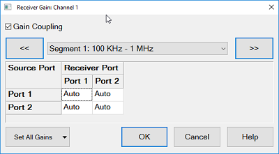
M980xA, P50xxA/B
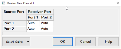
This dialog provides basic control receiver for a specific port.
This table consists of source port rows and receiver port columns. Each cell is corresponded to measurements in the active channel. (e.g. ‘Receiver port 1 – Source port 3’ is corresponded to S13, a1,3 and b1,3.)
The each cell sets the setting by the following drop down list.
-
Auto - (Default) Receiver gain is controlled automatically for each measurement points according to the input signal level.
-
High - Fix the gain setting at high
-
Low - Fix the gain setting at low
Set All Gains - Sets all cells at one time.
M983xA
Gain Coupling: When this is checked, the receiver gain can be set from Auto/High/Low. When this is not checked, the selection is disabled and RF attenuator and IF gain can be set independently at the Path Configurator.
Note: When the mult-port (multi-module) configuration is made by both M980xA and M983xA, the selection of Manual is not applied to M980xA because there is no RF & IF path configuration.
Note: In "Manual", the receiver gain for Bypass 20 GHz/44 GHz is fixed at a certain value according to the frequency.
Note: When the receiver gain is set at AUTO, the gain is fixed at LOW when the "RF In Switch" selects "External".
|
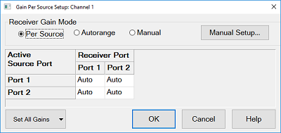
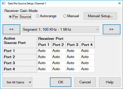
Reciever Gain Mode
|
Desctiption
|
|
Per Source
|
The receiver gain can be set at a specific port.
This table consists of source port rows and receiver port columns. Each cell is corresponded to measurements in the active channel. (e.g. ‘Receiver port 1 – Source port 3’ is corresponded to S13, a1,3 and b1,3.)
The each cell sets the setting by the following drop down list.
-
Auto - (Default) Receiver gain is controlled automatically for each measurement points according to the input signal level.
-
High - Fix the gain setting at high
-
Low - Fix the gain setting at low
Set All Gains - Sets all cells at one time
|
|
Autorange
|
The all receiver gains are set at Auto.
|
|
Manual
|
RF attenuator and IF gain can be set independently at the Path Configurator. Selection for High/Low/Auto is disabled.
|
|
|
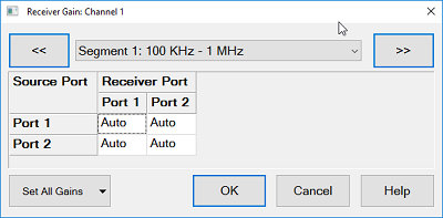
Receiver Gain for Segment Sweep dialog box help
|
|
In Sweep Segment Table Dialog, Check the check box of Receiver Gain.
M980xA, P50xxA/B
M983xA
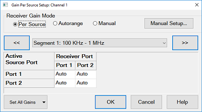
This dialog provides basic control receiver gain of the specified segment for a specific port in the segment sweep. The receiver gain in Segment Table dialog box should be turned on, then click Edit under Rev Gain column in the Segment Table,
The setting description is the same as the Receiver Gain above.
|