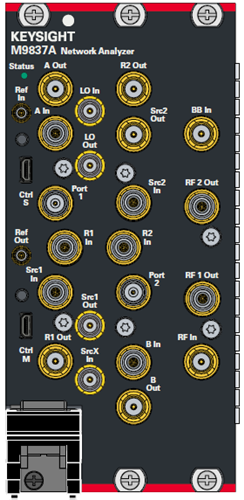
M9370A to M9375A
M9800A to M9808A
M9834A-205
M9834A-270 and M9837A-205/270
2 Port
2 Port (-200)
4 Port (M980xA-400)
6 Port (M980xA--600)
2Port
2 Port


M9370A to M9375A |
M9800A to M9808A |
M9834A-205 |
M9834A-270 and M9837A-205/270 |
||
|---|---|---|---|---|---|
2 Port |
2 Port (-200) |
4 Port (M980xA-400) |
6 Port (M980xA--600) |
2Port |
2 Port |
|
|
|
|
|
|
See Also
The following LED colors indicate the PXIe VNA status:
Green (solid) – Firmware is running but the PXIe VNA is NOT sweeping.
Green (blinking) - Each blink indicates a measurement sweep. The PXIe VNA may be sweeping faster than the indicator can blink.
Amber – Power is ON but the firmware is not running.
Red – A hardware error has occurred.
Off – Power is OFF.
All M937xA models are available with 2 test ports.
M980xA models are available with 2/4/6 test ports.
See data sheet for more information about the connector type and Input damage levels.
Ref In To use a external reference signal, either one below is required. It is not detected automatically.
From the soft front panel, click Setup > Internal Hardware > External Reference to switch external/internal reference.
From SCPI, use SENS:ROSC:SOUR.
Note: The external reference on the PXI chassis can be used by using SENS:ROSC:SOUR command.
Ref Out This connector outputs a 10 or 100 MHz frequency reference signal for use by other modules and test equipment.
See data sheet for more information about the connector type and Input/output levels.
100 MHz signal for Ref In and Ref Out is available from Reference menu or SCPI command.
Trig IN When enabled, the module accepts signals on this connector which indicates that the external devices is ready to be triggered.
Trig OUT When enabled, the module outputs signals on these connectors either before or after a measurement.
Trig Ready When enabled, the module outputs a 'READY' signal on this connector to other devices. This indicates that the module is ready to be triggered.
Learn more about External Triggering
For Daisy-chaining two or more modules. See the following information. See data sheet for more information about the connector type and Input damage levels. A 50 ohm terminations (p/n 1810-0118) is placed at the factory shipment.
M937xA Installation Guide.
M980xA, M938xA: https://www.keysight.com/find/m980xa-mm/
For Daisy-chaining two or more modules for multi-port or I/O adapter.
See the Path Configurator (RF and IF) for internal block diagram.
The following ports on the M9837A and M9834-270 are connected with RF semi-rigid cables at the factory shipment. These three cables must be connected at the service center calibration (performance test/adjustment)
Src1 Out and RF In (Cable P/N: M9830-61601)
Src1 In and RF 1 Out (Cable P/N: M9830-60602 for M9834A-270, M9830-61604 for M9837A)
Src2 In and RF 2 Out (Cable P/N: M9830-60603 for M9834A-270, M9830-61605 for M9837A)
Connector Name |
M9834A |
M9837A |
R1 Out, R2 Out, Src1 Out, Src2 Out, A Out, B Out, BB In, RF In , Src X In, LO In, LO Out |
SMA Female |
SMA Female |
RF1 Out, RF2 Out, A In, B In, R1 In, R2 In, Src1 In, Src2 In, Port 1, Port 2 |
3.5 mm Female |
2.4 mm Female |